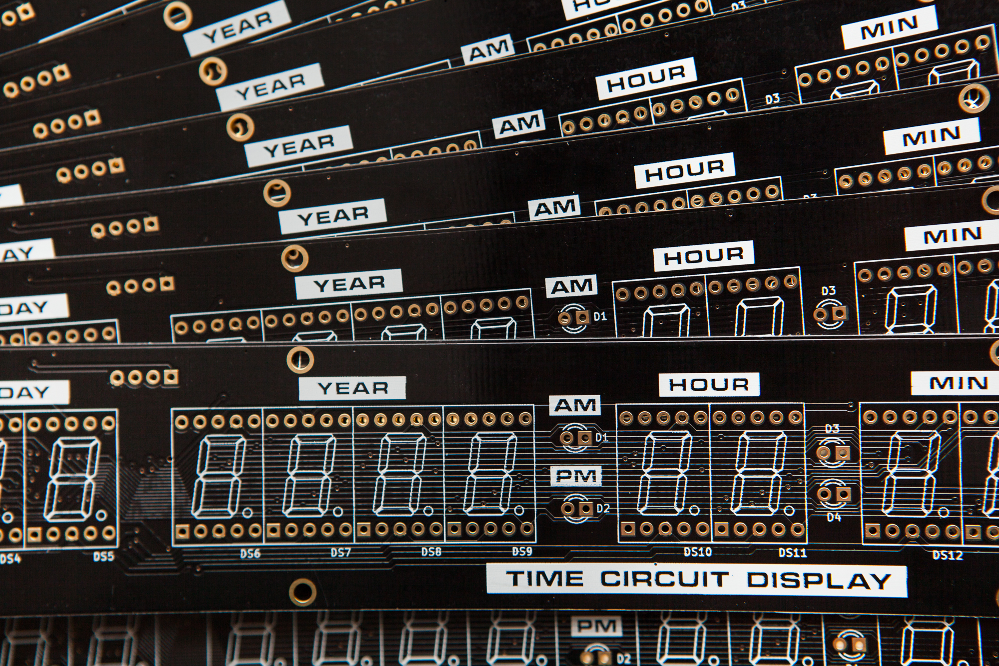
The time circuit display is a mix of three LED types: alphanumeric displays, seven-segment displays, and standalone 3 mm LEDs. Each one has a different height off of the circuit board and a different distance to the faceplate. I need to offset the components so all of the parts mate with the faceplate correctly, which requires sourcing LED standoffs and designing my own custom ones.
The Problem
The tallest components are the alphanumeric displays. Each alphanumeric display is 9.5 mm tall, while the seven-segment displays are 8 mm tall. This leaves a 1.5 mm gap that, if uncorrected, will recess the seven-segment displays from the faceplate.
The standalone LEDs are worse. Since the LED displays dwarf them in height, mounting the standalone LEDs flush with the circuit board would make them significantly recessed from the front of the faceplate by a full 5.5 mm.
Fortunately, there are solutions to both of these problems in the form of standoffs.
7-Segment Standoffs
Let’s start with the seven-segment standoffs, because they’re more complicated and more fun.
From what I can tell no one makes purpose-built standoffs for seven-segment displays, and why would they? Mixing segmented LED displays in a line is a strange thing, and in most devices where you’d have two components mounted at different heights you would use a daughterboard. As LED display standoffs are not commercially manufactured, I have to design my own.
Measuring Distances
Each seven-segment display is 8 mm tall, which puts them exactly 1.5 mm lower than the alphanumerics. This is the height of the standoff.
The first concern is whether the pins of each display will still make solid contact with the circuit board. The pins from each display are a finite length, and moving the display further away from the board leaves less of each pin to make contact.
According to the datasheet, each pin is 4 mm long (+/- 0.5). With the 1.6 mm thick circuit board, that leaves 0.9 mm of the pin sticking out above the back end of the board. While that may not sound like a lot, since the inside of each pin’s hole is plated it’s more than acceptable.
CAD Work
Kingbright generously provides 3D models of their displays. I imported a pair of the SC56-21 displays into my CAD program and started making some sketches.
Note: For critical work, never trust a CAD model you didn’t make yourself. Always check your dimensions against the datasheet.
The body of each display has four ‘posts’ in its corners. These are the parts that make contact with the circuit board and support the display. I’ll need to boost these by 1.5 mm while letting the pins pass through.
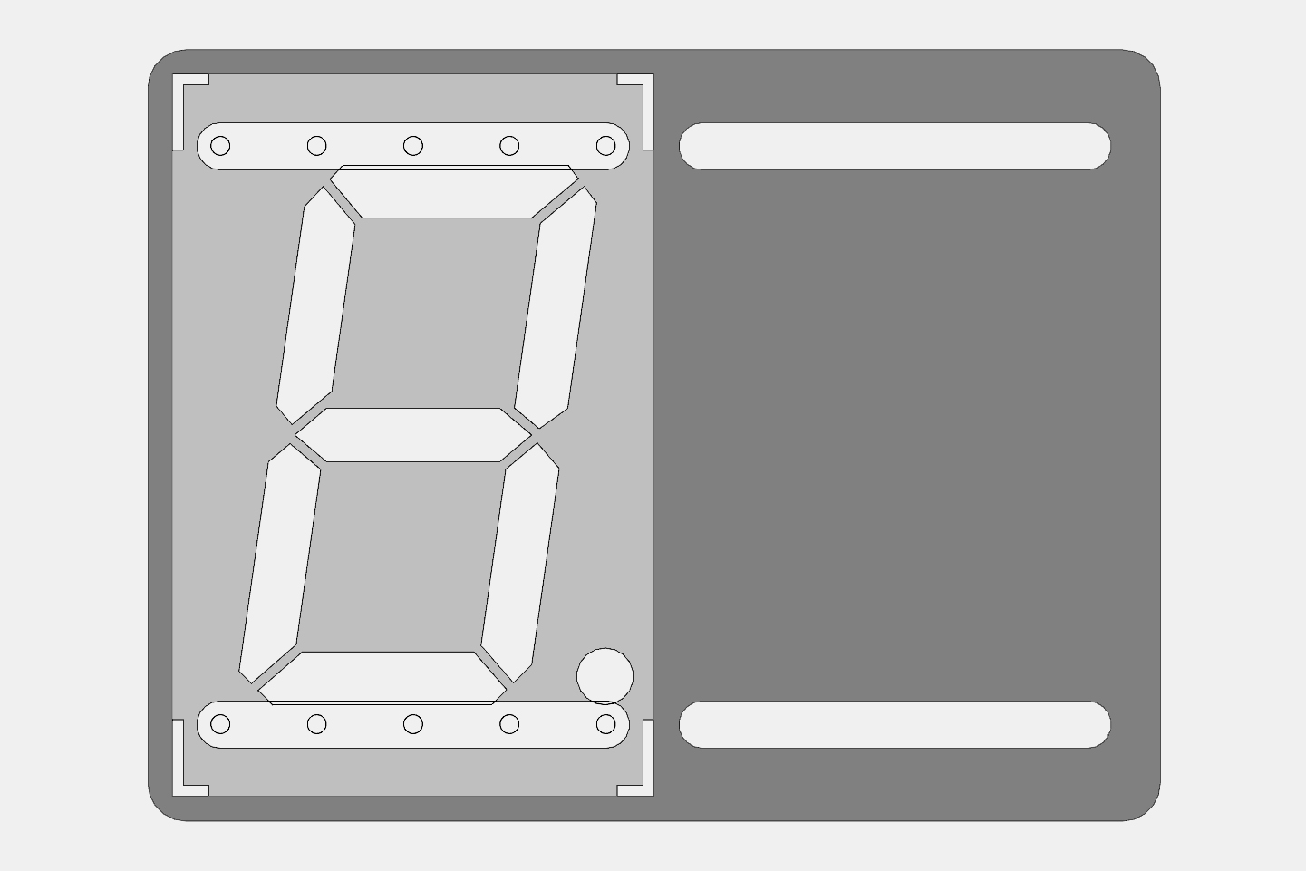
Standoff design for two displays with transparent view. The white corners are where the display rests on the standoff.
My design is simple. I took the outside edge of the display pair and offset it by 0.025″, and then made a slot cutout for the pins leaving 0.375 mm of extra space around each pin. (I know I’m mixing units here, but since the display width is dimensioned in inches and the pin diameter in millimeters I let it slide.) Each spacer covers two seven-segment displays, as there is a zero-thickness gap between the corner posts. I mirrored the design to make a four-display version for the ‘Year’ display.
The design is entirely flat. The only reason I could see for adding vertical features would be retaining clips for the displays, although this isn’t necessary. The spacers are wide enough that the display’s pins will hit the edges of the pin slot before it slides off, and once soldered in place the display won’t be able to wiggle side to side.
Lasercutting
I didn’t want to make 15 of these precise little things at home, mostly because cutting fine details in moderately thick plastic is a pain. Or at least, it’s a pain to do by hand – it’s a breeze for a lasercutter. With lasercutting, I can get my design produced inexpensively with no setup tooling costs.
The supplier of choice here is Ponoko. With the automated tools on their website, I can upload a design file, select a material and get a quote instantly. They charge by total line length, or in other words the amount of time your design will take to produce on their machines.
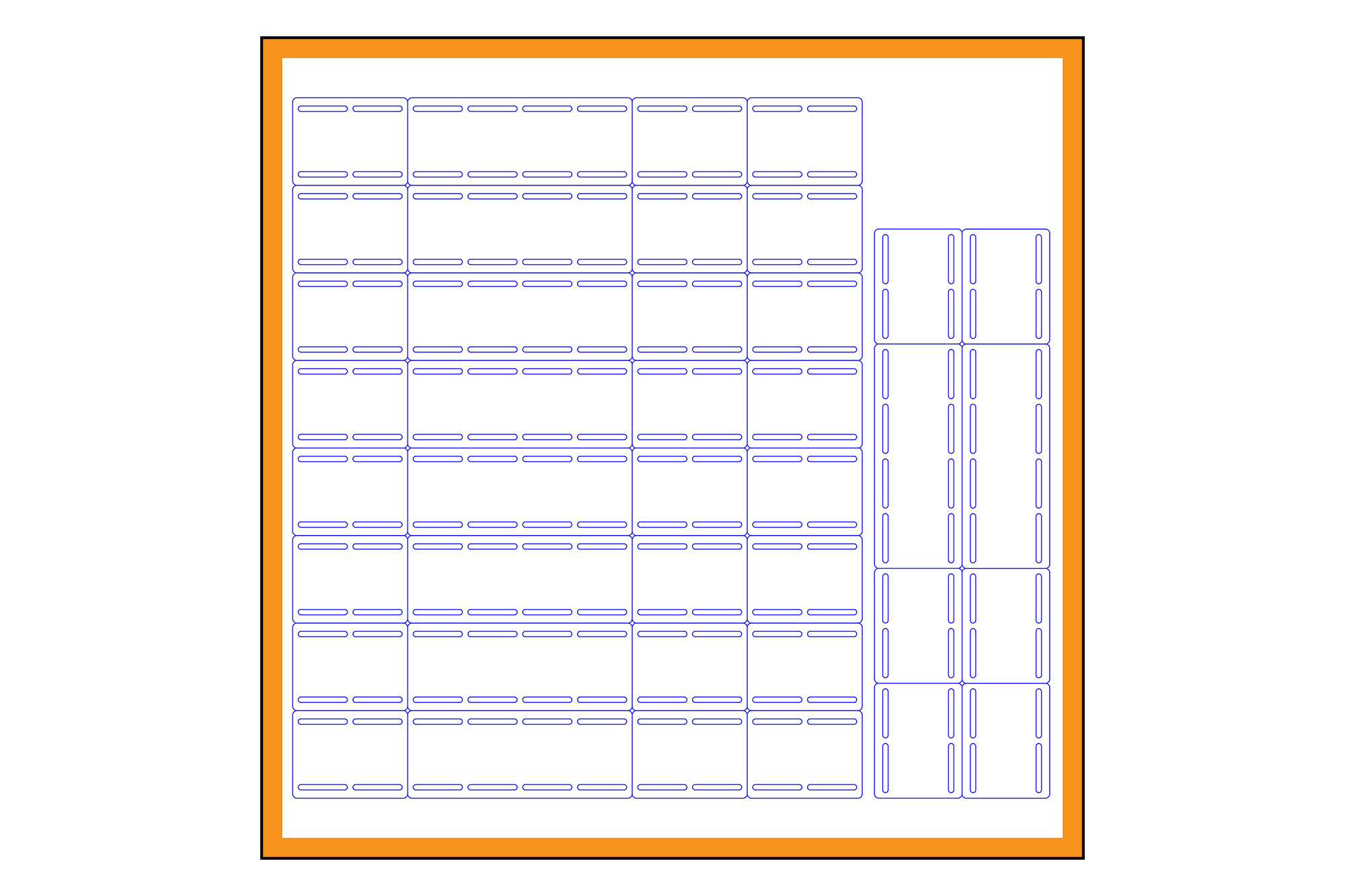
The standoff layout for a sheet of 7.1″ x 7.1″ black acrylic. Ten full sets with shared edges.
I exported a 2D version of the design from my CAD program and imported it into Adobe Illustrator. After downloading Ponoko’s design templates, I imported the file and started laying out copies. Since they charge by line length, you can do things like overlay edges and delete one side to save on space and cost. Ponoko doesn’t do any design offsetting to account for the laser’s kerf as it requires knowledge of design intent, but my design will function fine losing 0.2 mm of material on line centers.
I was able to fit 10 sets of standoffs on their smallest material size, which is 7.1″ by 7.1″. While I only need 3 sets for the project, I already had to pay for material costs and shipping so the extra 7 sets only set me back a few dollars.
Ponoko charged me $4.50 for the 7.1 by 7.1″ (181 by 181 mm) sheet of 1.5 mm black acrylic, $14.60 for the lasercutting, and $8.25 in shipping (the cheapest option). All told, that’s $27.35 for 10 sets of standoffs. Not cheap compared to commercially produced electronics parts, but quite inexpensive for having a custom design manufactured.
Arrival and Fitment
When working with any new manufacturer it’s wise to order a few test samples before putting in a full-sized order. For this project where the “full order” was already small, I took my chances with the complete order right out of the gate.
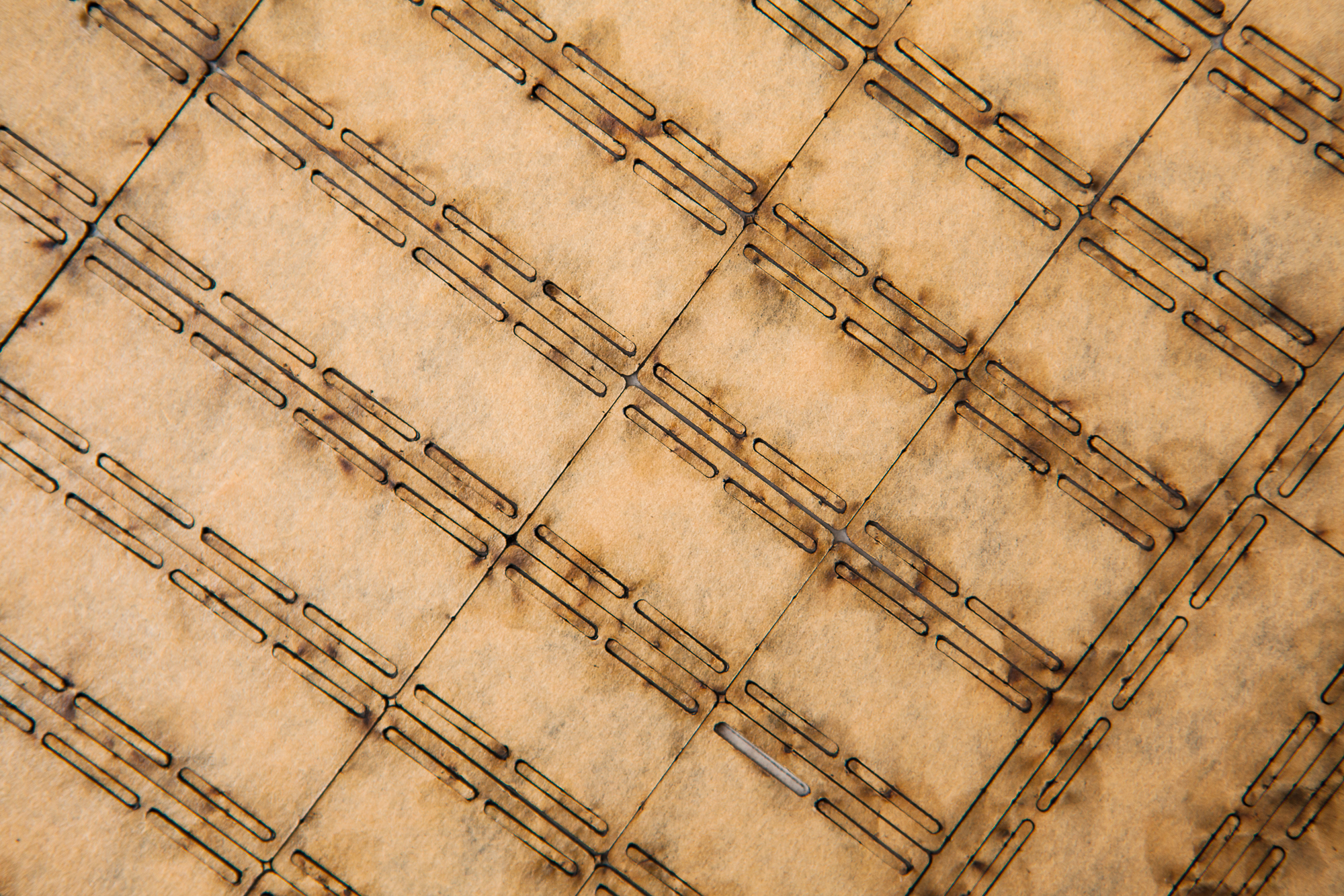
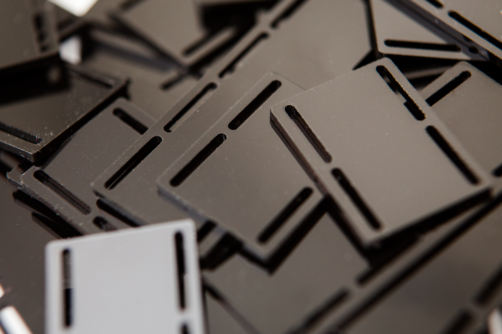
Lasercut 7-segment display standoffs, still covered in protective paper.
It took 10 days from placing the order to the standoffs arriving at my doorstep. The entire 7.1″ square piece was included in the envelope with all of the waste pieces still attached. Both sides of the acrylic were covered by protective paper and the back of the board had an adhesive sheet to keep everything in place. From some cursory measurements the spacer dimensions are as-designed, +/- a few thousands for tolerance.
After pulling off a few spacers and peeling away the protective paper, it was time to test them out. The result?
They work perfectly! The LED displays fit with plenty of clearance around the pins and there is no way for a display to slip off. With the time circuit display circuit boards still in the mail, I used a piece of perfboard I had lying around to test the spacers with the displays. You can see that they fix the height difference almost perfectly.
Single LED Standoffs
While the seven-segment standoffs are more fun, the lone LEDs are easier to deal-with because stand-offs for single LEDs are used regularly in industry.
First, I needed to figure-out the heights of each LED. Unlike the LED displays, the standalone LEDs aren’t flush with the faceplate. Instead, they poke through the faceplate. The only question is by how much.
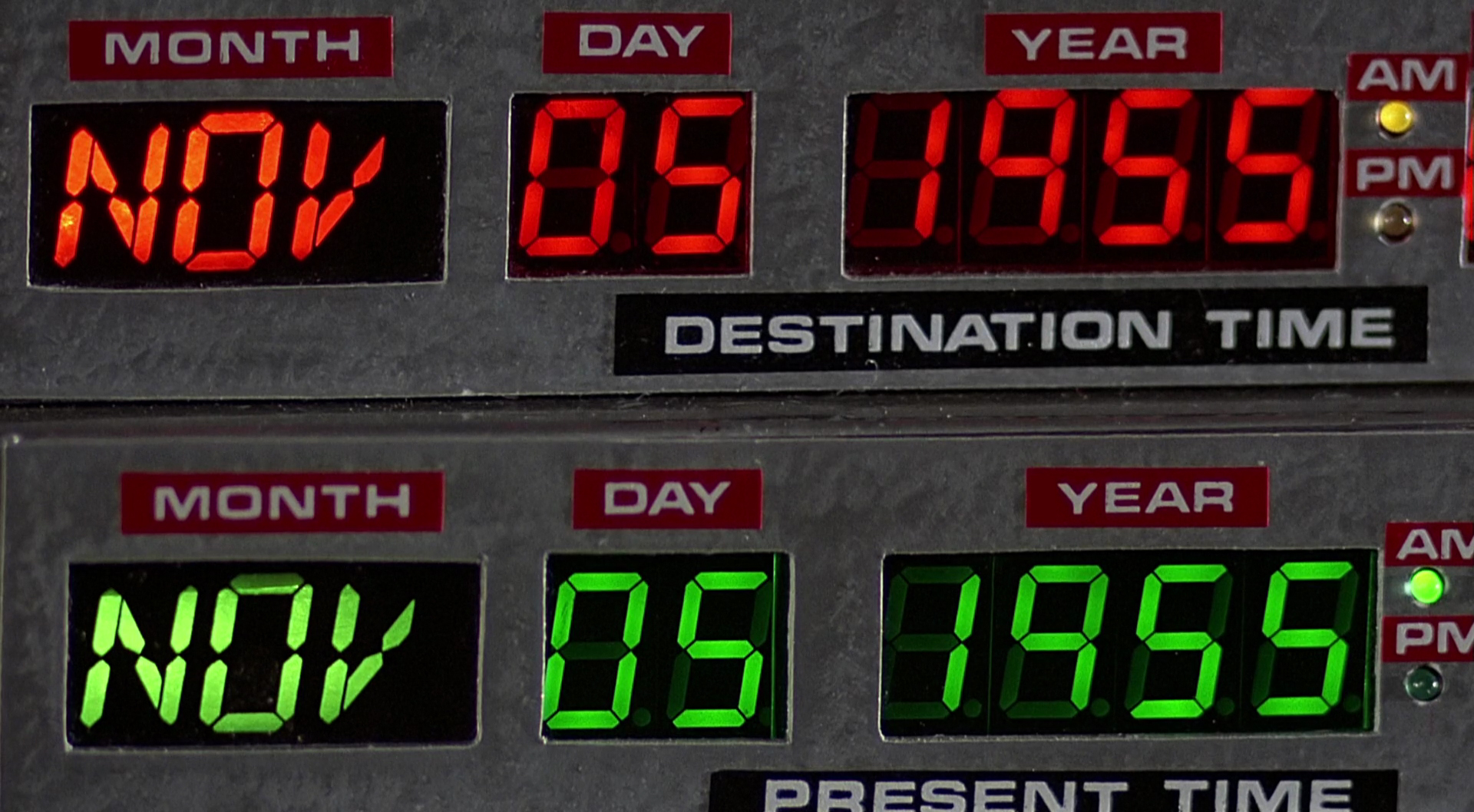
Extreme close-up of the time circuits shutting off after Marty arrives in 1955. Note the depth of the standalone LEDs. 00:34:37:02.
I rewatched all three Back to the Future movies trying to figure this out. I was looking for a close-up side-shot of the time circuits, something where I could see the distance from the LED bulb to the faceplate. There are a few side shots through the passenger door during the train sequence in the third movie, but nothing close enough to see the individual LEDs. Instead, I’ll need to make a judgment call based off of the straight-on shots.
The frame grab above is the best I could find of the LEDs in the original prop. This is when the time circuits shut off, shortly after Marty arrives in 1955. The prop was built by hand and each LED varies, but to my eye it looks as though the LEDs stick out just slightly (< 0.050″) from the front of the faceplate.
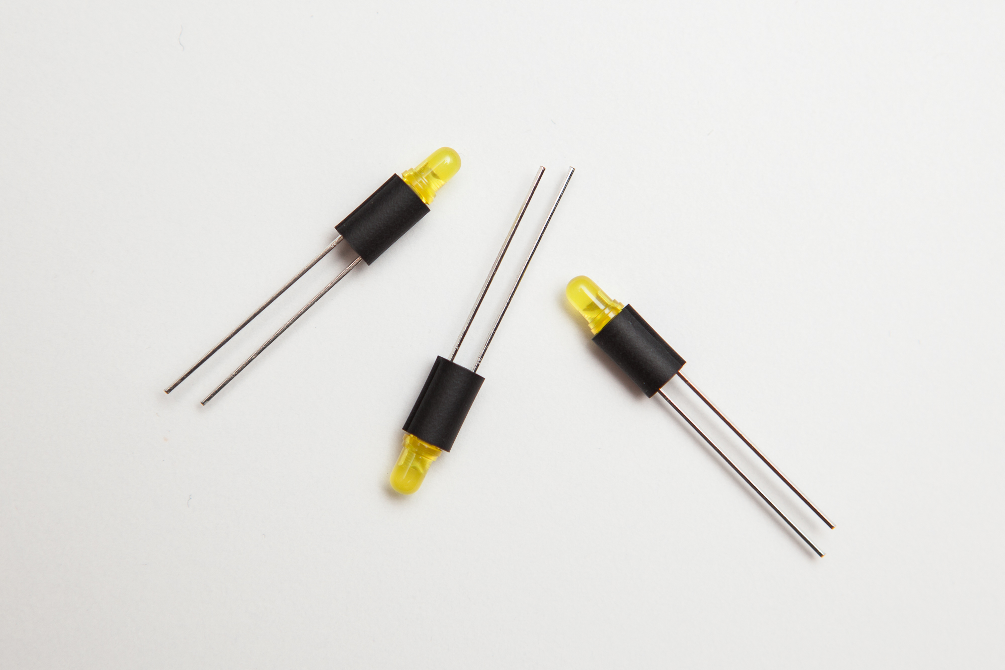
3 mm LEDs with standoffs.
Now it’s time to do a bit of math. The 3 mm LEDs I have sitting around are 5.2 mm tall from their base to the top of the bulb. The faceplate is offset from the PCB by 9.5 mm (height of the alphanumeric display), and I’m planning on using 0.050″ (1.27 mm) thick aluminum sheet metal for the faceplate itself. With these measurements, if I want the LEDs perfectly flush I would need a standoff that is 5.57 mm tall (0.219″). I want mine to stick out just a tiny bit, so I decided on 1/4″ standoffs (6.35 mm) which makes them stick out only 0.031″.
I searched DigiKey and Mouser for a suitable standoff and settled on an ‘ELM 2’ standoff made by Bivar. For the quantities I’m ordering, each one is around $0.10. I’ll need 4 per board for a total of 12.
Alternate Solutions
There’s more than one way to skin a cat. Although I eventually decided on ordering custom lasercut parts for the seven-segment displays, I had a few other ideas on how to solve this problem.
So why not a daughterboard?
As I mentioned above, I wanted to avoid splitting the display circuit board into a mother and daughterboard. I had a few reasons for this:
- Complexity: I would need to design two circuit boards and work out the mounting and electrical connections between them. It’s certainly possible, but it would be a bit messy and require a number of extra parts. One complete circuit board is significantly cleaner.
- Strength: A single circuit board bridging the gap between both case halves will be stronger, which is important considering that the circuit board is taking the load for almost the entire side of the case that is removed. In an ideal world very little force is going through the case, but I don’t want a stray bump to ruin the prop.
- Cost: A daughterboard means I need to have two circuit boards manufactured and order additional hardware to mount and connect them. Standoffs are cheaper.
I’m sure in almost all other cases where you have two user-facing parts at different heights a daughterboard would be the right solution, but it wasn’t here.
Why use standoffs at all?
There’s an obvious solution to these variable heights that doesn’t require any standoffs: since the parts are through-hole, I could just solder the parts higher on the board and let the pin leads support them.
The issue is that this would transfer any force on the LED displays to the pads on the circuit board, which risks delamination. In an ideal world you want any force on the part to be transferred to the circuit board’s substrate, not the copper.
I could have also just left the displays at two different heights, but that looks lazy. It’s something I can easily fix, so I’m going to do what I can to build this right.
Conclusion
The time circuit display PCBs are still in the mail, but I’m slowly inching my way closer to having all three displays assembled and running. Exciting times ahead!
