With power taken care of, the next step is to connect the data lines (step, direction, and drive select) to the Arduino. The easy way to do this is to carefully count the pin numbers, attach a female header cable to each pin, connect the step / direction pins to the correct Arduino numbers, and join the grounded connections on a breadboard.
That’s the quick and easy way. But it’s also:
A.) Tedious to set up / take down
B.) Possible to make a wiring mistake
C.) Prone to disconnects
How do we fix all three of these problems? We build a breakout board!
Planning
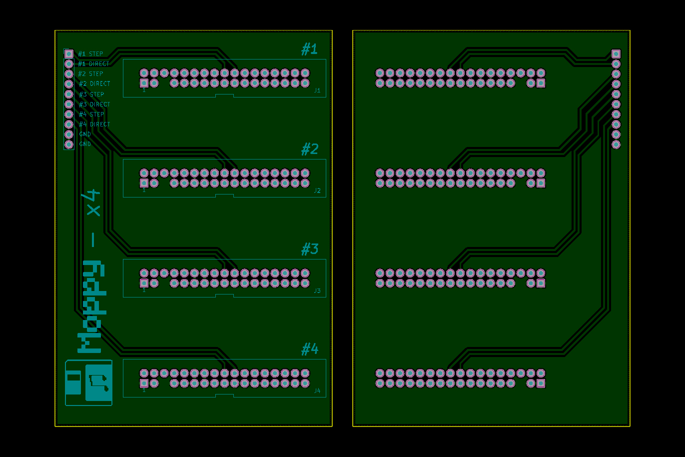
Top and bottom of the board. Traces are only on the bottom – shown on top side for reference.
In its simplest form, a breakout board is a PCB that gives you easier access to a component. For musical floppies, where we’re only concerned with 3 pins (+ ground), this should be a piece of cake.
Since we only need a few pins out of 34, it would make sense to build some custom cables that connect to a 4-pin header. But that is less useful and somewhat more work-intensive than using IDC connectors and cables. Plus, if the design works with IDC connectors then anyone could use the board for their own Moppy project without building custom cables.
I knew what I needed to make, so the first step was to figure out the form factor.
Moppy Arduino Shields
My first thought was to build some sort of “shield”. In Arduino parlance, a shield is a generic, dedicated PCB that has the same dimensions as an Arduino Uno, and expands its capabilities while sitting directly on top of the board. A “motor shield” gives the Arduino the ability to control motors, a “network shield” gives the Arduino the ability to connect to the Internet, etc. etc.
So why not build a “Moppy” shield? Because the Uno is small, and the IDC-34 connectors used by floppy drives are big. You would only be able to fit 1 or 2 connectors on a PCB the size of the Uno, leaving room for the headers. I wanted to drive eight floppy drives from one Arduino, and I didn’t want to make a shield that was just filled of intermediary connectors to go to another PCB.
I think it would be fun to design a Moppy shield that supports 1 or 2 drives, but that can be a project for another day.
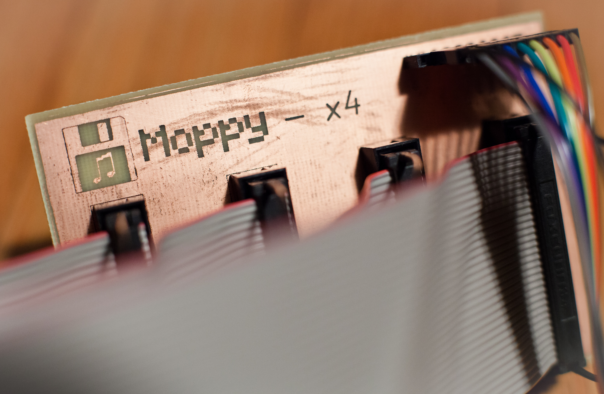
Moppy Breakout 4x
What I eventually settled on was a completely independent breakout board. I had 100 x 70 mm copper-clad boards on hand from the Adalight project, which are the perfect size to fit four IDC connectors with some breathing room for the cables. A 0.1″ header on the side could be used for the jumpers to the Arduino.
For each IDC connector, the connections are as follows:
- Pin 20 (Step) to header
- Pin 18 (Direction) to header
- Pin 14 (Drive Select A) grounded
- Pin 12 (Drive Select B) grounded
- All odd # pins grounded
Grounding both drive select pins allows the use of both twisted (standard) and straight IDC cables. It may also enable using more than one drive on a single cable, although I don’t have any multi-drive cables to test this with.
As an aside: note that the pin labeling for the drive select pins is a bit odd. Pin #12 on the drive itself is the drive select pin, but the standard 7-wire twist in the floppy cable makes it so that pin #14 on the PC-side connects to it. The straight-through cable (which makes pin #12 go to pin #12) is for the ‘B’ drive, after the standard twist.
Eventually it will make sense to improve upon this and add some supporting electronics (input protection, LED indicators, etc.), but to start I just wanted to connect everything directly and get things up and running.
EAGLE to KiCAD
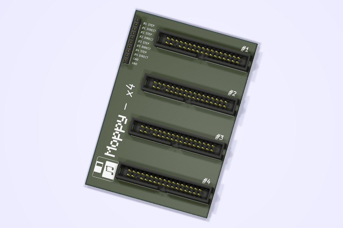
Using KiCAD’s 3D rendering tool
I dipped my feet into the world of PCB design with the Adalight project, during which I learned the basics of how to use CadSoft EAGLE.
Unfortunately for me (and the hobbyist electronics community), EAGLE was purchased by Autodesk, and at the start of the new year they promptly got rid of the low-level commercial licensing and locked all commercial use into a subscription model. Which, quite frankly, sucks for hobbyists like myself who might think of one day trying to sell a few boards here or there. I didn’t want to spend upwards of $100 a year indefinitely for that opportunity.
In place of EAGLE, I decided to try and learn KiCAD. KiCAD (pronounced “Key CAD”) is a fully open-source electronics CAD program. It’s not the easiest switch from EAGLE, as it’s very segmented. In KiCAD, to put two parts on a PCB you need to: create a schematic, then a net list, then associate components to footprints, and then import the net list in the PCB editor. In EAGLE, it’s simply a matter of pressing “Generate/switch to board”. That’s just an example, but the KiCAD suite loves separating functionality into its own dedicated programs.
This segmentation combined with the somewhat clunky interface (why are so many things accessible ONLY with a keyboard shortcut?!) makes it a somewhat rough switch. But unlike EAGLE, KiCAD is 100% free with no limitations, and always will be.
Using KiCAD, I took a few days to design the breakout board. The board has four IDC connectors and a single 1 x 10 0.1″ female header strip for connecting to the Arduino. I also added a custom logo for good measure.
Etching and Aligning Front + Back
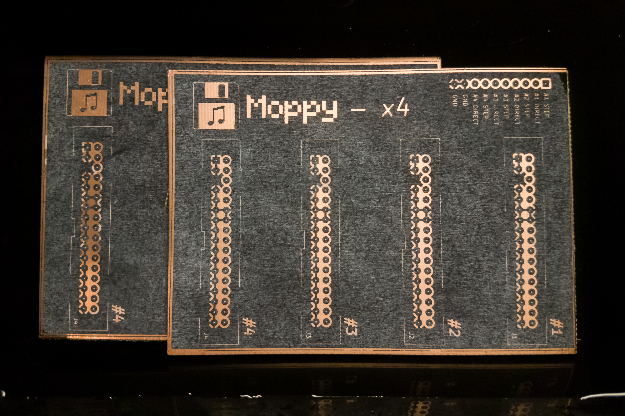
For home etching, I used the same toner transfer process that I did for the Adalight board: laser print on glossy paper, transfer using a clothes iron on its hottest setting for 5 minutes, and sponge etch using ferric chloride.
The only thing I changed for these boards was making some ‘registration marks’ for aligning the front and back transfer paper. Although the ‘front’ of these boards isn’t used, the only copper clad boards I had were double-sided, and I didn’t want to etch the entire side away. So a second ground plane with labels it is!
For the Adalight boards, I transferred and etched one side, then drilled out the mounting holes in the corners. I used the mounting holes to align the second side, which was a bit tedious but seemed to work alright.
With these boards, I wanted to see if I could etch both sides at once so I would only need to mess with the nasty chemicals once. I found a nice crosshair registration mark using a quick Google search, and in Photoshop I laid out three marks on both the top and bottom of each side of the board. I offset one mark to act as a key, so I wouldn’t accidentally etch one side upside-down.
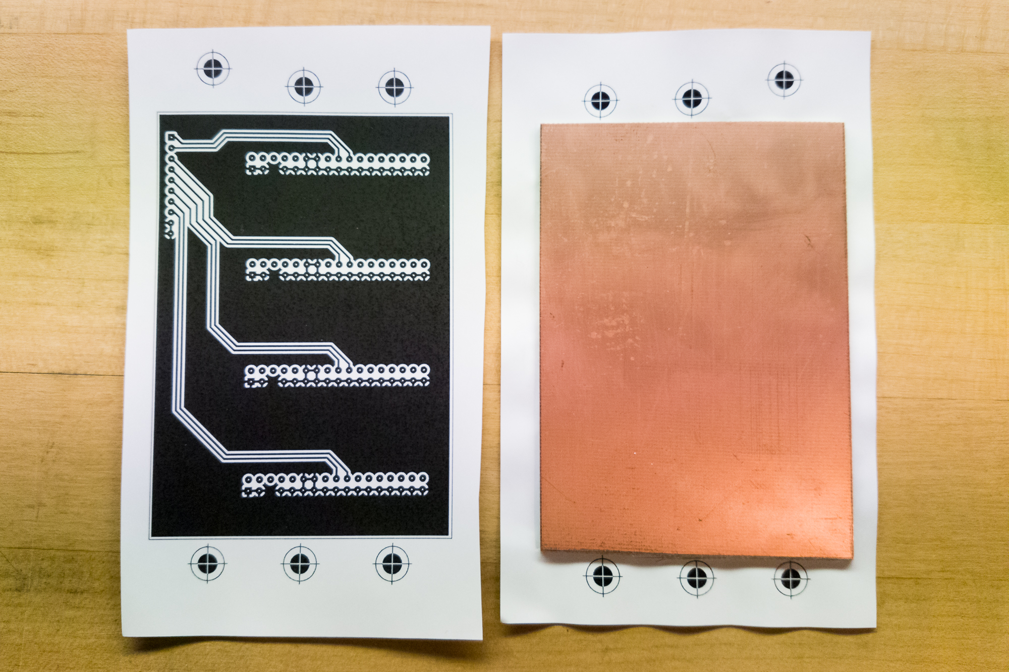
After I transferred one side, I flipped the board over, and aligned the second side with the registration marks. I used a bit of kapton tape to attach the paper edges and then ironed the second side.
The paper needs to bend around the board, so it’s not a perfect process. But it was far easier than trying to align both sides with mounting holes, and the resulting boards are matched well enough to work.
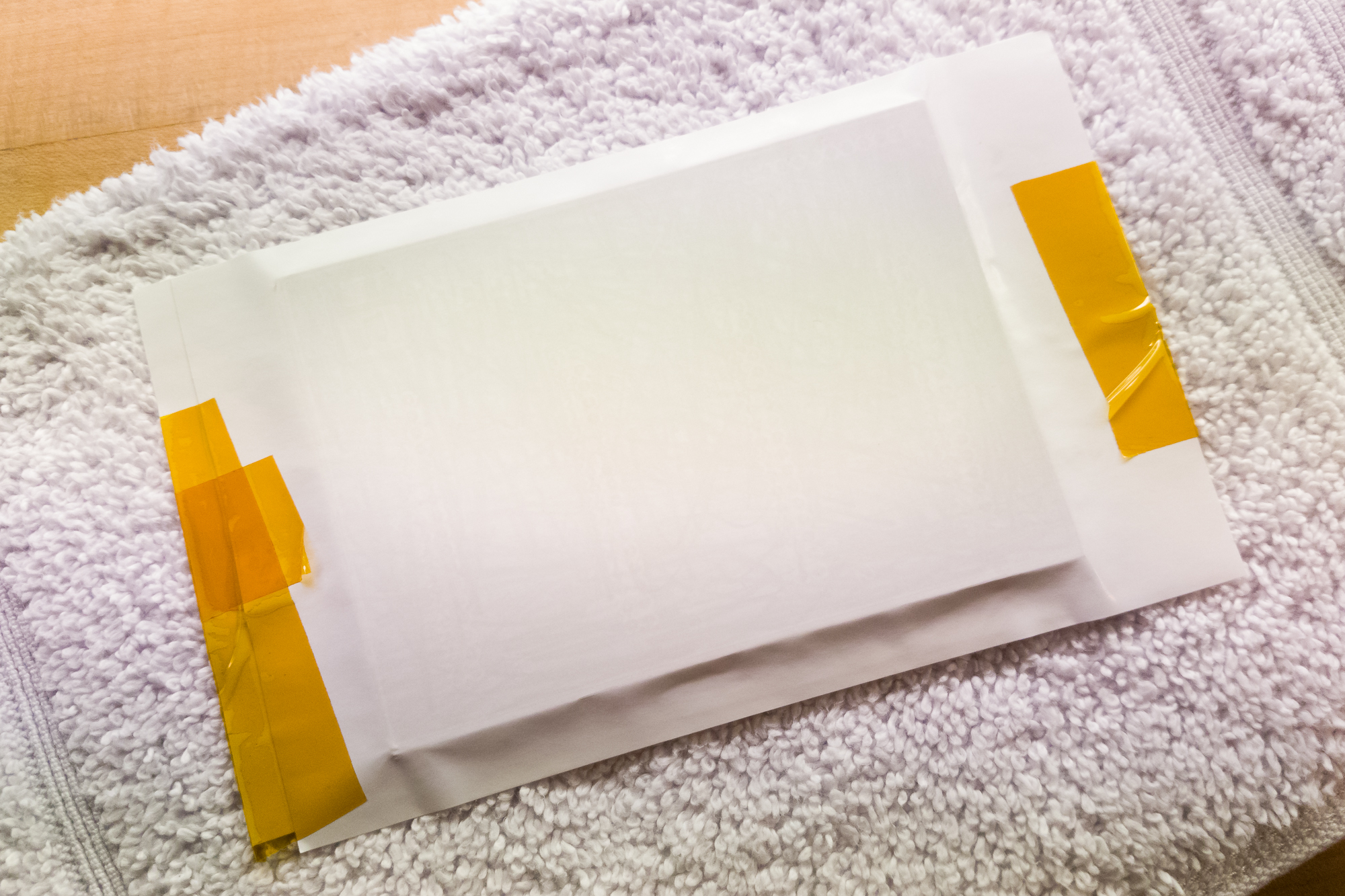
With the toner transferred, etching both sides at once was a breeze. See my post from the Adalight project with more details on sponge etching. After etching and thoroughly rinsing the boards, I verified the traces’ continuity using a multimeter and checked for shorts.
Adding Connectors
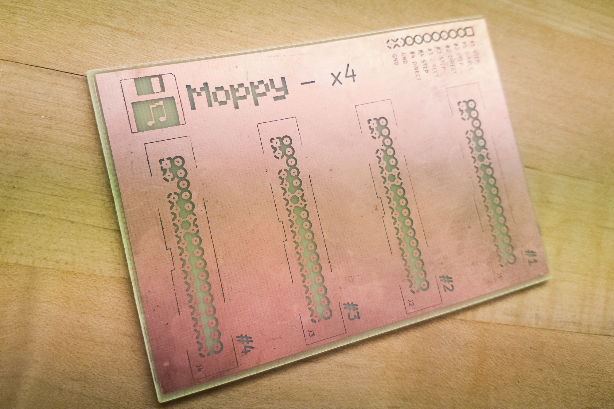
With the boards etched, the final step was to drill out the pin holes and solder on the connectors.
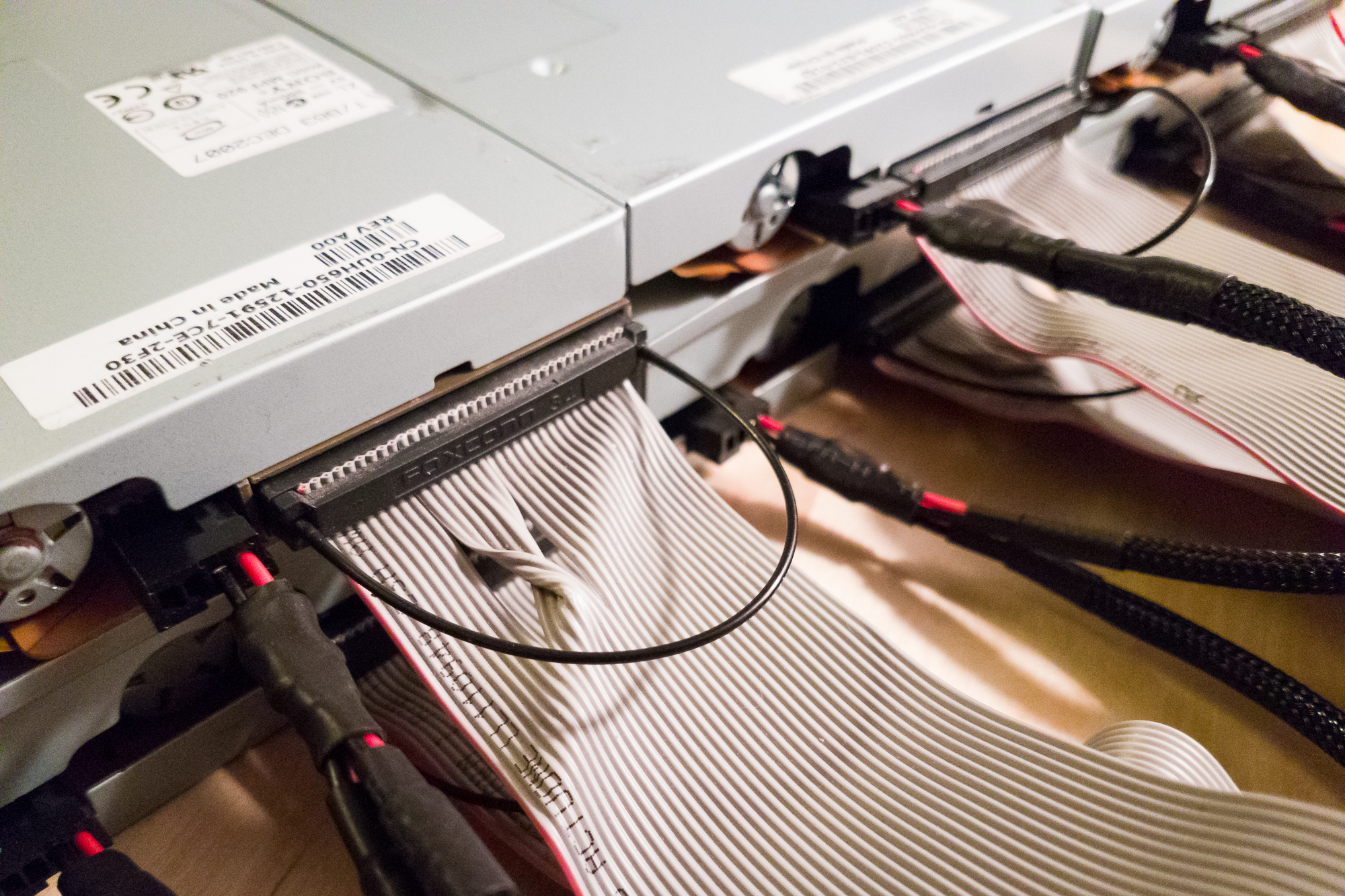
I ordered my connectors from DigiKey. For floppy drives, the 34-pin IDC connectors are keyed on both the PC and the floppy side (pins 5 and 3, respectively) so that you don’t plug in the cable backwards. The 34-pin connectors I ordered have all 34 pins, so it was necessary to pull out the #5 pin on each connector. This only took a few seconds with a pair of needle-nose pliers and a firm, steady pull.
(I purposefully did not include the #5 pin on the PCB so that it wasn’t possible to accidentally solder on a non-keyed connector.)
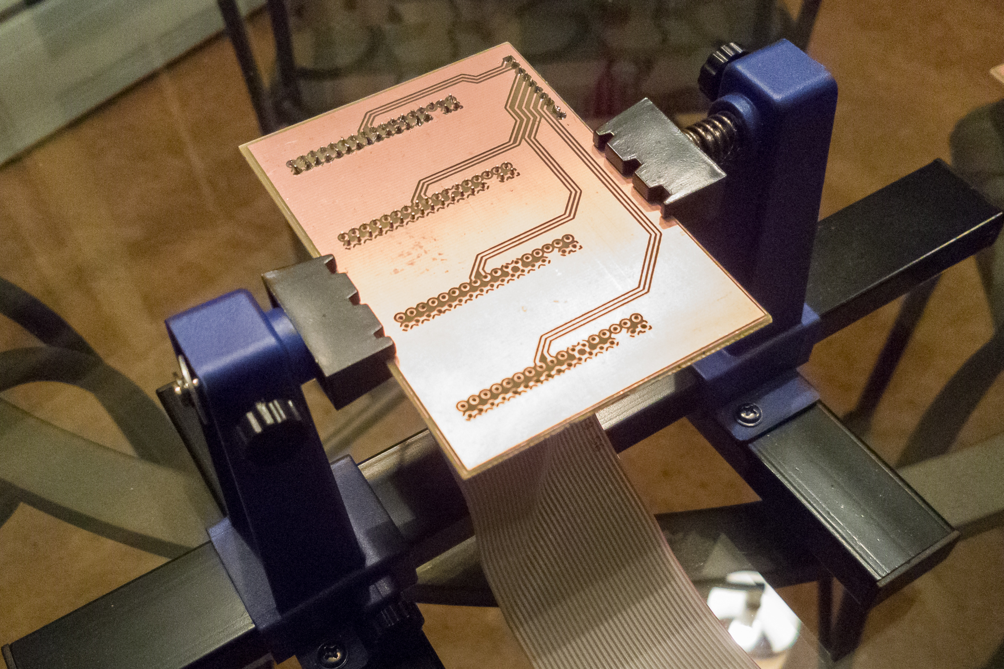
Using a PCB vices makes soldering a lot easier
For these first boards, I decided to drill and solder all of the pins for completion’s sake. If I were to do it again, I would remove some of the pins around the middle of the connector just to save on time. Soldering 146 pins per board takes awhile!
Conclusion
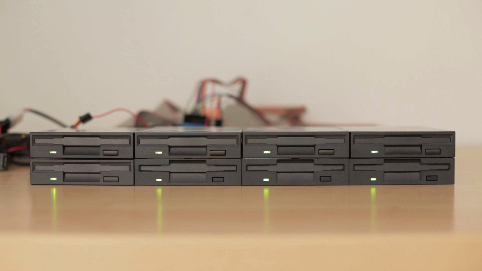
After getting the boards together, it was simply a matter of connecting the IDC cables and the Arduino. And now one musical floppy drive becomes eight! I’m really happy with how these turned out; they make it a breeze to set everything up.
If I do design a board with this many pin holes again, I’ll probably look into getting it manufactured elsewhere. These were a pain to drill and solder.
At some point I’ll push the KiCAD files to GitHub so that anyone can build them. I need to get around to cleaning up the files a bit before then, though.
With the cables and the data lines done, I now have a functioning 8 drive orchestra. I’ll put a video together soon!
Parts List
- 34 Pin IDC Connector (4x)
- 10 Pin 0.1″ Female Header
- Glossy Laser Paper (for toner transfer)
- Double-Sided Copper Clad Boards
- Ferric Chloride Etchant
Note that some of these are Amazon affiliate links which help fund the content on this site. Thank you for your support!
