I’m slowly working on an embedded library that emulates an Xbox 360 controller, and one of the features I wanted to add is LED animation support that mimics the “ring” LEDs on the original controller. The first step of this is determining what animations exist and then measuring the timing intervals for each LED.
Measuring Setup
To do this I’m going to use an official Microsoft Xbox 360 Wireless Controller. I’m assuming the animations are the same with a wired controller, but that’s harder to test with since the LEDs lock up if there’s no host USB communication.
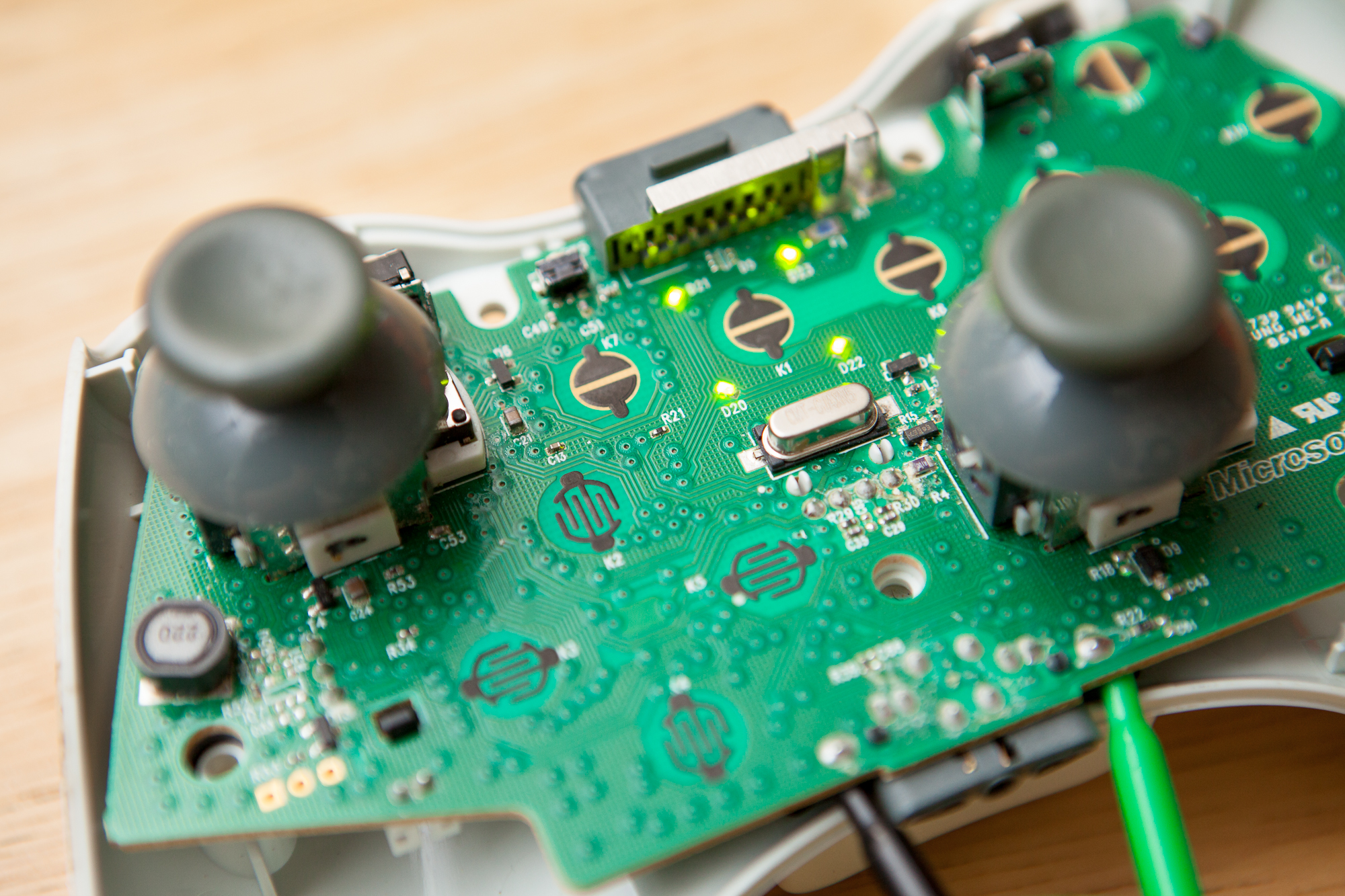
To measure the LED timing, I disassembled the controller by removing the seven T8 security screws from the back and lifting off the shell. After disconnecting the two rumble motors, I removed the circuit board from the top shell and reinstalled it in the back shell. This exposes the LEDs on the top and allows me to use the built-in battery pack. For ground reference and power, I attached hook grabbers to the spring leads for the battery pack and ran them to a breadboard.
The LEDs themselves are active-low, meaning that they always receive the battery high voltage (3V) and have their current sunk through the microcontroller’s I/O pins to toggle them on. These pins float when the LED is off, so I attached 10 kΩ pull-up resistors to the positive battery lead to keep the signal high.

To measure the LED timing I used a knockoff Saleae logic analyzer running at 24 MHz. Holding the measuring leads in my hand, I placed them carefully on LED pads 1 and 2, then used the auto-triggering function of the Saleae software to capture 30 seconds of LED data. From the captured data I then measured the animation timing intervals.
Note that the LEDs are also pulse-width modulated for brightness using a 3.92 kHz frequency and a 35% duty cycle (255.12 µs period – 90.33 µs on, 164.79 µs off). This doesn’t affect how I’m measuring the LED animations, but it’s useful to note nonetheless.
Searching
The searching animation plays whenever you turn on the controller, before it successfully connects to a wireless receiver. It consists of a slow blink that is occasionally interrupted by a fast blink. Both animations blink all four LEDs in tandem.
Slow Blink
The slow blink animation has a period of 1 second, with all four LEDs on for 300 ms and off for 700 ms. It typically blinks 16 times before changing to fast blink.
Fast Blink
The fast blink animation has a period of 600 ms, with all four LEDs on for 300 ms and off for 300 ms. It typically blinks 4 times before changing back to slow blink.
On Connection
The four LEDs on the controller’s ring correspond to player numbers for the console/receiver’s four supported controllers. This allows the end-user to pass around controllers and keep track of which player is which.
When the controller has successfully connected to a receiver, it will light up only the assigned player LED, blink it 3 times, and then leave it illuminated. The timing of these blinks matches the “fast blink” searching animation – 300 ms on, 300 ms off. Timing for all four players is identical.
Pairing
The pairing animation can be triggered by pressing down the small “connect” button by the charging port (above “back”, next to LB). This animation indicates that the controller is ready to pair with a new console or receiver.
During this animation the four LEDs “chase” each-other clockwise in a rapid motion. Each LED is on for 100 ms and off for 300 ms (400 ms to complete one cycle). The animation will run for approximately 45-50 cycles before returning to the “searching” animation if no pairing is found.
Low Battery
The low battery animation consists of pairs of opposite LEDs that rapidly alternate (1+4, then 2+3). The LEDs alternate at the same pace as the “fast blink” searching animation – 300 ms for pair 1, 300 ms for pair 2. This repeats approximately 7 times before returning to the previous animation.
USB Pattern Values
While all of these animations are observable just by turning on a wireless controller and manipulating some of the buttons, they can also be triggered by a series of packets sent by the USB host. Here are the list of commands:
0x00	 All off
0x01	 All blinking
0x02	 1 flashes, then on
0x03	 2 flashes, then on
0x04	 3 flashes, then on
0x05	 4 flashes, then on
0x06	 1 on
0x07	 2 on
0x08	 3 on
0x09	 4 on
0x0A	 Rotating (e.g. 1-2-4-3)
0x0B	 Blinking*
0x0C	 Slow blinking*
0x0D	 Alternating (e.g. 1+4-2+3), then back to previous*
Patterns marked with an asterisk (*) will go back to the previous pattern after they have completed.
I pulled this list from the (now defunct) Free60 Wiki via the Internet Archive’s Wayback Machine. These ‘pattern’ values are the the third byte in a USB packet sent by the host to the controller’s first OUT endpoint, the first two being 0x01 (the message type) and 0x03 (the message length), respectively. I was able to verify some of these using a software USB analyzer on my PC, while others I cross checked against known working implementations such as the USB Host Shield Library.


