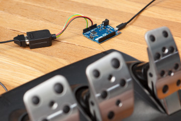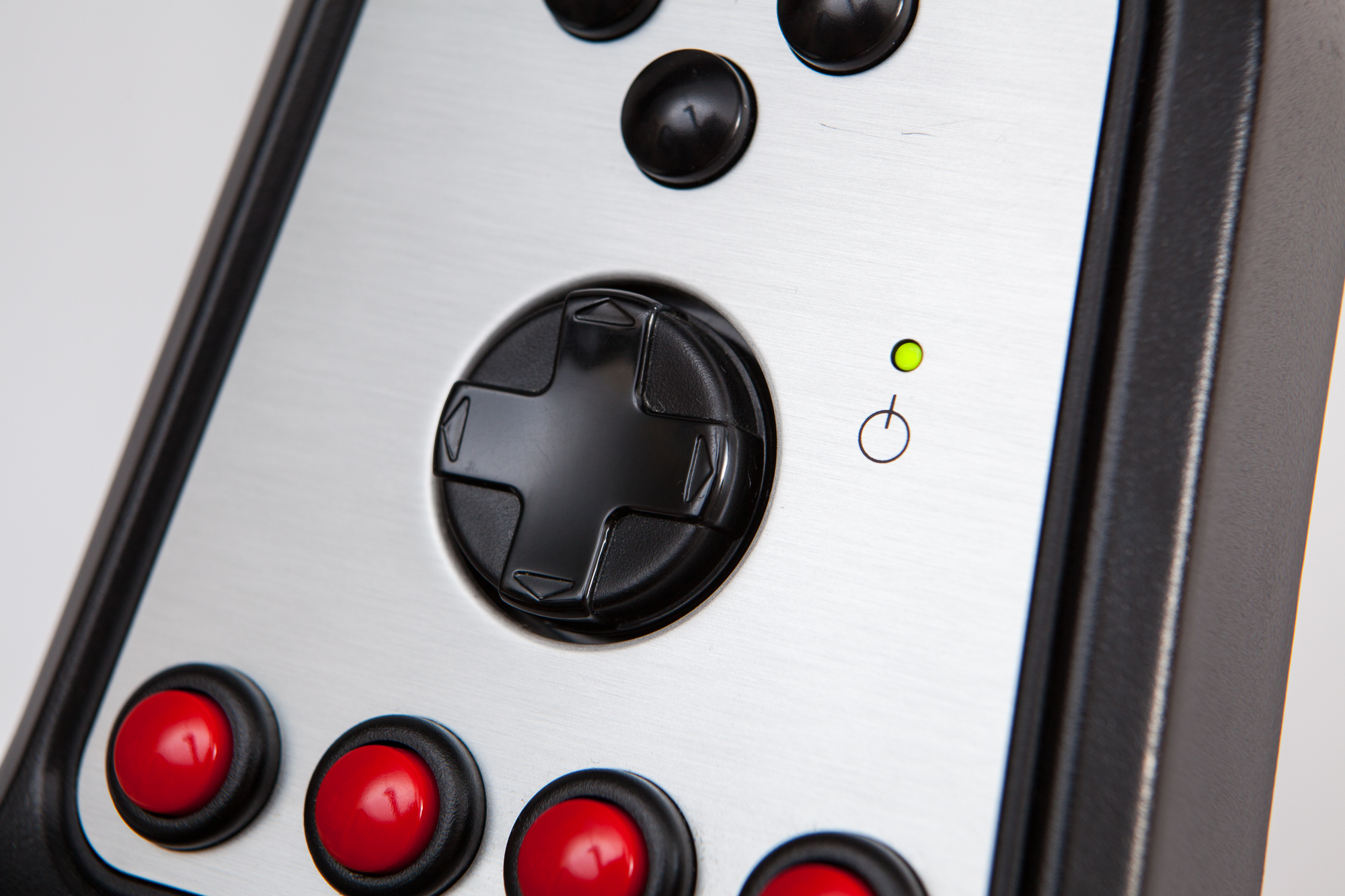
If you’ve followed my instructions to build a DIY USB adapter for your Logitech G25 or G27 shifter, you might have noticed something that may seem a little odd: the power LED doesn’t light up!
Don’t worry, nothing is broken and you haven’t done anything wrong – it’s normal that the power LED doesn’t turn on with these adapters. The power LED has its own pin, and since it’s not needed in order to read from the shifter I didn’t add it to the tutorial. But don’t fret! I can show you how to turn on the power LED, and even how to control it from the Arduino for some fun effects.
Connector Wiring
You’ll need another piece of 22 AWG solid-core wire, about 7 inches long. Strip the ends and connect one end to pin 5 of the DE-9 connector.
The shifter has a 330 Ohm resistor in series with the LED, so if you want you can connect the pin directly. Although if you have a G25 shifter, I would recommend adding a 100 Ohm resistor in series so that the power LED and the sequential mode LED have the same brightness. You can also add a resistor in series to reduce the brightness if you’d like.
To keep things solderless, I’d suggest using some Wago 222 Lever-Nuts. These are easy to use – open the lever, insert the wire, then close the lever to secure it. You could also use a solderless breadboard, although the wires aren’t going to be as well-secured.
(These are affiliate links. As an Amazon Affiliate I earn from qualifying purchases.)
Arduino Wiring
There are two options for connecting to the Arduino.
The simple option is to connect the wire (or the other pin of the resistor) directly to ground. As long as the Arduino has power, the LED will be on. If you want the LED on all of the time, that’s all you need to do.
The more fun option is to connect the wire to one of the Arduino’s digital I/O pins. The library supports this in the code if you edit the Pin_ShifterLED in the shifter examples. The LED will be on by default, but you can change its state by calling the setPowerLED(bool) function and then calling update() to push the change.
Testing LED Control
Now that we can control the LED, here’s some simple code to test it. You can insert these snippets into the loop() function of the examples to try them out.
On / Off
I’ve mapped the first and second red action buttons to turn the LED on and off on demand. Remember that the update() function needs to be called to refresh the shifter’s state in the code (and thus to change the LED).
// turn the LED on
if (shifter.getButton(ShifterButton::BUTTON_1) && shifter.getButtonChanged(ShifterButton::BUTTON_1)) {
	shifter.setPowerLED(1);
}

// turn the LED off
if (shifter.getButton(ShifterButton::BUTTON_2) && shifter.getButtonChanged(ShifterButton::BUTTON_2)) {
	shifter.setPowerLED(0);
}
Blink
We can also animate the LED! Here, I’m using the built-in Arduino millis() function to flash the power LED when the third red action button is held down.
// flash the LED
if(shifter.getButton(ShifterButton::BUTTON_3)) {
	const unsigned long BlinkTime = 50;  // ms
	const unsigned long now = millis();
	static unsigned long prev = now;

	if (now - prev >= BlinkTime) {
		shifter.setPowerLED(!shifter.getPowerLED());  // invert
		prev = now;
	}
}
else if(shifter.getButtonChanged(ShifterButton::BUTTON_3)) {
	shifter.setPowerLED(0);  // turn the LED off when released
}
Morse Code
We can even do something silly, like flashing the LED to Morse code. This snippet will flash out “SOS” in Morse code whenever the fourth action button is pressed.
// display a Morse code message ("SOS")
if(shifter.getButton(ShifterButton::BUTTON_4) && shifter.getButtonChanged(ShifterButton::BUTTON_4)) {
	// Morse code uses a base timing unit for all symbols. A dot is high for
	// 1 unit, a dash is high for 3 units. There is a 1 unit gap between symbols
	// (dots and dashes), a 3 unit gap between characters, and a 7 unit gap
	// between words.
	//
	// The duration of the timing unit is based on a words per minute (WPM)
	// standard using the word "PARIS" (.--. .- .-. .. .../), which is
	// exactly 50 units long.
	//
	// The ARRL (American Radio Relay League) uses a standard of sending
	// transmissions at 18 WPM. That means at 18 WPM sending 50 units we
	// need 900 time units per minute. 60 seconds / 900 = ~0.066 seconds
	// per unit, or approximately 66 ms.

	const unsigned long t = 66;

	// using macros here so this code block is short but still independent
	#define LED_ON  do { shifter.setPowerLED(1); shifter.update(); } while(0)
	#define LED_OFF do { shifter.setPowerLED(0); shifter.update(); } while(0)

	#define DOT  do { LED_ON; delay(t);   LED_OFF; } while(0)
	#define DASH do { LED_ON; delay(t*3); LED_OFF; } while(0)

	#define SGAP delay(t)
	#define CGAP delay(t*3)
	#define WGAP delay(t*7)

	DOT;  SGAP;
	DOT;  SGAP;
	DOT;  CGAP;

	DASH; SGAP;
	DASH; SGAP;
	DASH; CGAP;

	DOT;  SGAP;
	DOT;  SGAP;
	DOT;  WGAP;
}
Because this is just a demo, this code uses the blocking function delay() for simplicity which prevents the shifter from doing anything else for ~2 seconds while the message is flashed out.
Making a Shift Indicator
Let’s do something a little more useful (but only a tad). Many racing sims have the ability to export live telemetry data. This often includes things like your car’s position, tire temperatures, suspension travel, and of course… engine RPM.
I wrote a quick Python script that reads the RPM data from Forza Horizon 5 and then uses PySerial to control the LED on the Arduino. This is hobbled slightly by the fact that the Forza RPM data reports the max RPM displayed on the gauge rather than the max RPM before hitting the rev limiter, but it’s good enough for demonstration purposes:
import socket
import struct
import serial
from enum import Enum

udp_ip    = "127.0.0.1"
udp_port  = 5300

uart_port = "COM5"
baudrate  = 115200

shift_threshold_min = 0.77
shift_threshold_max = 0.9


class Indicator(Enum):
	OFF   = ' '
	ON    = '+'
	FLASH = '!'

if __name__ == "__main__":
	print("\nLogitech G25/G27 Shift Light for Forza Horizon 5")
	print("www.partsnotincluded.com")
	print("------------------------\n")

	sock = socket.socket(socket.AF_INET, socket.SOCK_DGRAM)
	sock.settimeout(1)  # seconds
	sock.bind((udp_ip, udp_port))

	ser = serial.Serial(
		port=uart_port,
		baudrate=baudrate
	)

	state = Indicator.OFF
	connected = False

	try:
		while True:
			try:
				data, addr = sock.recvfrom(1024)
			except TimeoutError:
				if not connected: print("Waiting for data...")
				continue

			if not connected:
				print()  # spacing
				connected = True

			# this is the max RPM on the gauge, **NOT** the rev limiter. irritatingly.
			rpm_max     = round(struct.unpack_from("<f", data,  8)[0], 0)
			rpm_idle    = round(struct.unpack_from("<f", data, 12)[0], 0)
			rpm_current = round(struct.unpack_from("<f", data, 16)[0], 1)

			# rescale current RPM as percentage of idle to max
			if rpm_max <= 0.0 or rpm_current <= rpm_idle:
				rpm_percent = 0.0
			else:
				rpm_percent = (rpm_current - rpm_idle) / (rpm_max - rpm_idle)
				rpm_percent = round(rpm_percent, 3)

			new_state = Indicator.OFF
			if rpm_percent >= shift_threshold_max:
				new_state = Indicator.FLASH
			elif rpm_percent >= shift_threshold_min:
				new_state = Indicator.ON

			if state != new_state:
				state = new_state
				ser.write(state.value.encode('utf-8'))

			print("\r" + "RPM %: " + "{:.2%}".format(rpm_percent), end='')
			if(state == Indicator.ON):
				print(" SHIFT", end='')
			elif(state == Indicator.FLASH):
				print(" SHIFT!!!", end='')
			else:
				print(" " * 10, end='')

	except KeyboardInterrupt:
		ser.close()
On the Arduino, I added a small block of code to read the data from the USB serial interface and then set the LED accordingly:
static bool blink = false;

const int c = Serial.read();
if(c == ' ') {
	shifter.setPowerLED(0);
	blink = false;
}
else if(c == '+') {
	shifter.setPowerLED(1);
	blink = false;
}
else if(c == '!') {
	blink = true;
}

if(blink) {
	const unsigned long BlinkTime = 50;
	const unsigned long now = millis();
	static unsigned long prev = now;
	if(now - prev >= BlinkTime) {
		shifter.setPowerLED(!shifter.getPowerLED());
		prev = now;
	}
}
You can test the LED modes using the Arduino serial monitor (send [space], +, or ! to set the LED to off, on, or blink respectively). Or run Forza Horizon 5 with the data telemetry output IP set to local (127.0.0.1) with port 5300.
Conclusion
Hopefully you can see how easy it is to add support for the shifter’s power LED to these DIY USB adapters using the Sim Racing Library. At the end of the day, you can use the shifter’s built-in LED as any other indicator. Use your imagination!
Have you made anything fun using the library’s LED support? Leave a comment below!