McCree Hammershot Controller: Buttons and Rotary Encoder
The planning for the controller is complete and the disassembly of the Nerf gun is done. This is where the real fun begins – modifying the revolver and starting the electronics.
Lately I’ve been watching my fair share of Twitch, and one of my favorite streamers is a kiwi by the name of Rudeism. Although he’s quite an entertaining streamer in his own right, one of his gimmicks is that he plays games “wrong”. That is to say, he likes to play games in a way that’s not standard – something he calls “AltCtrl”. He’s played Overwatch’s Winston with bananas, Skyrim with voice-only controls, and Player Unknown’s Battlegrounds (PUBG) with a frying pan, just to name a few of his many AltCtrl projects. You can find his streams on Twitch.
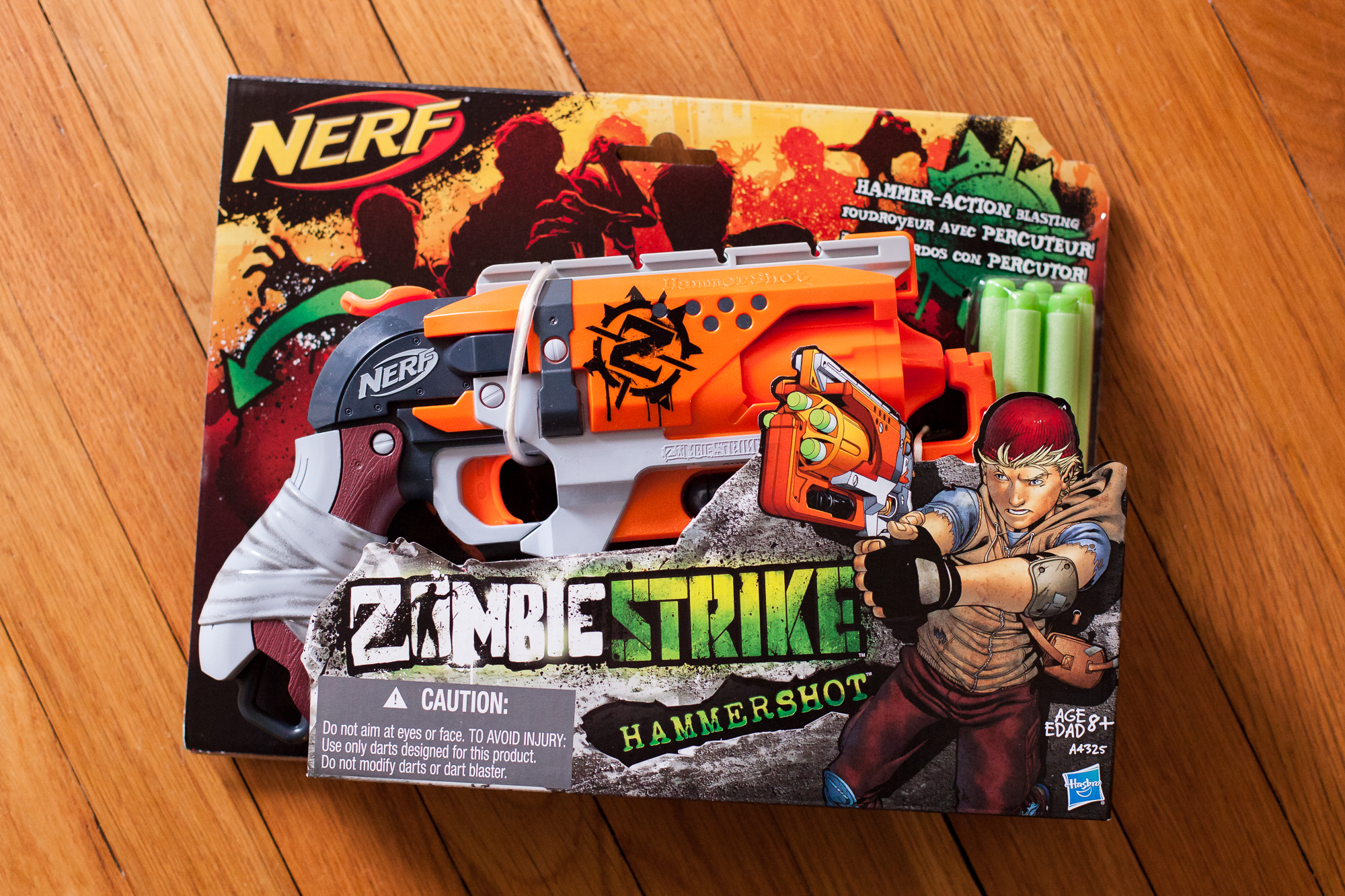
I think the whole idea of “AltCtrl” is quite intriguing, and it would be fun to build my own controller that matches the animations in a game. I’m going to try doing just that by making my own controller for Overwatch out of a Nerf Hammershot revolver.
(more…)Now that all of the time circuit display electronics are in the mail it’s time to talk about programming the display. This starts with learning how to control LEDs with the Holtek HT16K33 integrated circuit (IC), which I’m using as the display’s matrix driver.
(more…)The time circuit display is a mix of three LED types: alphanumeric displays, seven-segment displays, and standalone 3 mm LEDs. Each one has a different height off of the circuit board and a different distance to the faceplate. I need to offset the components so all of the parts mate with the faceplate correctly, which requires sourcing LED standoffs and designing my own custom ones.
When it came time to start the programming for my time circuit displays, I needed a library of characters for segmented LED displays so that I could not only show the time, but also display strings of text. Maybe I wasn’t looking hard enough or I was looking in the wrong place, but much to my dismay I couldn’t find a readily-accessible library to use. So I’ve made my own and I want to share it so others don’t run into this same problem.
It’s been a long road to get to this point, but I’m finally at the stage where I can design the printed circuit board (PCB) for the time circuit display.
I’ve chosen the LED displays, found a matrix driver, and determined the final positions for each LED display on the faceplate. The next step in the time circuits project is to build a dedicated circuit board for each display. This process starts with creating an electrical schematic.
Now that I know exactly what I’m looking for, it’s time to buckle down and try to find some real-world LED displays for the time circuits.