Researching LED Displays for the Time Circuits
Now that I have a tentative plan for how I’m going to control all 300-some LED segments, the next step towards making this prop a reality is to figure-out the specifications for the LED displays.
I have no formal education as an electrical engineer, so one of my first steps for the time circuits project is figuring out how to drive the large number of LED segments that make up the three time circuit displays.
The goal of this project is to build my own personal replica of the DeLorean’s “Time Circuits”, as featured in the Back to the Future movie trilogy. I’ll need to build custom time circuit displays, a custom keypad for changing the date, and screen-accurate enclosures. To make everything function, I’ll need to design and program some embedded circuits to control it all.
Last spring before this blog was a thing, I created an “Oddshot Button” using a hacked Staples Easy Button. The button was simple – while watching a Twitch stream, a press of the button would instantly create a video clip of the last 30 seconds using the Oddshot service.
A few months later Twitch debuted their own ‘Twitch Clips’ service, and Oddshot has since fallen out of use. So I decided to remake this project to work with Twitch Clips!
If you’re looking for a big project button, you can find it at Staples.
Introduced as part of their “That Was Easy” marketing campaign in 2005, the easy button is a large red button that, when pressed, says the phrase “that was easy” via a small speaker.
Its low price of $6.99 is enticing. What if instead of buying a purpose-built large button, we can repurpose an Easy Button for our projects instead?
With power taken care of, the next step is to connect the data lines (step, direction, and drive select) to the Arduino. The easy way to do this is to carefully count the pin numbers, attach a female header cable to each pin, connect the step / direction pins to the correct Arduino numbers, and join the grounded connections on a breadboard.
That’s the quick and easy way. But it’s also:
A.) Tedious to set up / take down
B.) Possible to make a wiring mistake
C.) Prone to disconnects
How do we fix all three of these problems? We build a breakout board!
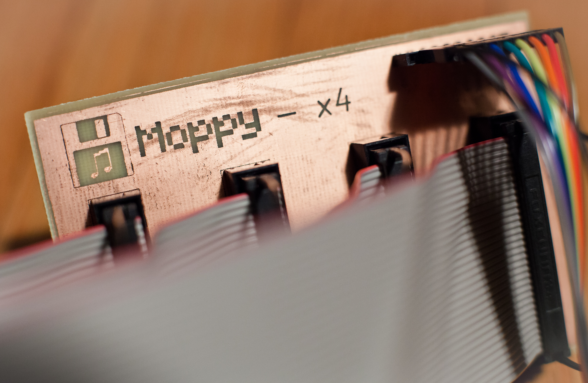
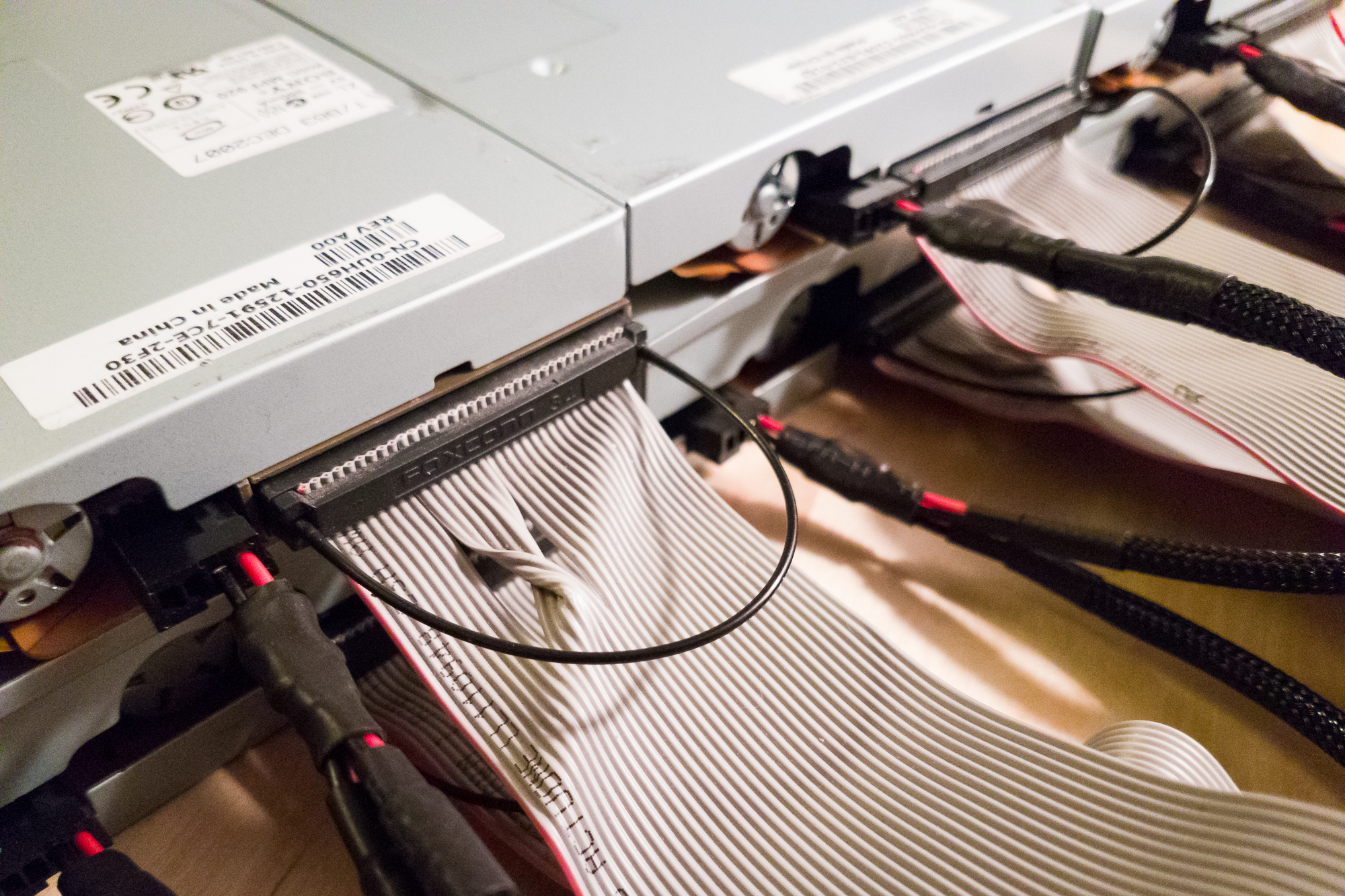
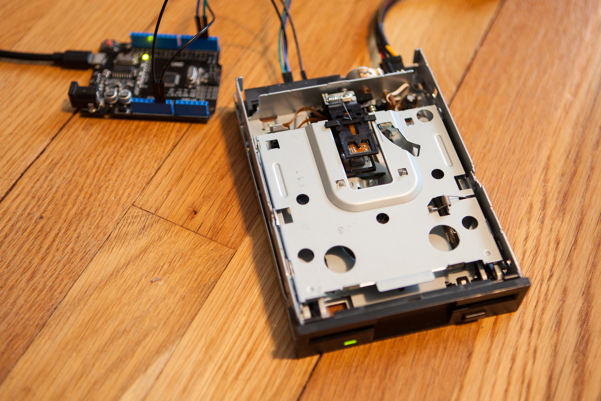
So far, I’ve figured out how to get a single floppy drive to make music. But why play music on one floppy drive when you could play it on eight?
An Arduino Uno with Moppy can drive a maximum of nine drives when connecting directly to the I/O pins. If you have nine drives on hand and an Arduino Uno, it’s simply a matter of connecting the data lines to the Arduino (step, direction, and drive select), and the power lines to a 5V supply.
That’s the simple and messy way. The more complicated, cleaner way is to build dedicated custom power cables that fit the floppy drives, and custom circuit boards to connect to pre-made 34-pin IDC cables.
I prefer the cleaner way, so I decided to build my own floppy power cables.
With enough ingenuity, you can turn just about anything into a musical instrument. A few years ago, some inspired makers did just that using floppy drives. By manipulating the drive’s read-head motor, you can produce different pitches and therefore play music!
After doing a bit of research this seemed surprisingly simple, so I thought I would take a crack at it.