I’ve figured out what LED displays I’m going to use and I’ve found the case they’re going to fit in, but before I can design a custom circuit board I need to figure-out how they’re going to be spaced in the enclosure.
Faceplate Technology
As I’ve previously mentioned, the enclosure used for each time circuit display in the original film was from LMB Heeger, Crown Royal Series part number CR852. Because these cases have their assembly screws on the front-facing side, the Back to the Future production crew opted for a cleaner look using a custom made faceplate.
You can see in the “hero” shot that there is a faceplate on top of each enclosure with a gel behind it. The spacing for the holes on these faceplates are what I need to figure-out. Although I’m not building the faceplates themselves quite yet, these openings dictate the positions of the LED displays on the circuit board.
Photogrammetry Measurements

Once again we return to the hero shot from the original film to make some measurements. I need the width of each display opening and the distance between each one. Altogether these should add up to be 8.5″, the width of the LMB enclosure.
After putting the “hero” shot into CAD, I resized it so the “Present Time” enclosure was 8.5″ across and drew a series of colinear horizontal lines with their endpoints meeting at the edges of each display opening. If you remember back to the photogrammetry I did for the LED displays, you’ll know that these are rough numbers – the photo isn’t perfectly head-on, there is some lens distortion, and the resolution isn’t great. But it does give me a good idea as to the ratios of everything.
I can make this better by making logically similar measurements equal, and using some judgment to round everything to 0.005″ while still keeping the relative sizes and making sure everything adds up to 8.5″. Here are the results:
| Description | Measurement (in) | Normal Measurement (in) |
|---|---|---|
| Edge to 'Month' | 0.224 | 0.215 |
| 'Month' Opening | 1.658 | 1.650 |
| 'Month' to 'Day' | 0.232 | 0.235 |
| 'Day' Opening | 0.987 | 1.000 |
| 'Day' to 'Year' | 0.344 | 0.350 |
| 'Year' Opening | 2.016 | 2.000 |
| 'Year' to 'Hour' | 0.507 | 0.500 |
| 'Hour' Opening | 0.968 | 1.000 |
| 'Minute' to 'Hour' | 0.350 | 0.335 |
| 'Minute' Opening | 1.000 | 1.000 |
| 'Minute' to Edge | 0.215 | 0.215 |
Using the same image / method, I measured the display opening height and the spacing between the standalone LEDs. For the LEDs I measured center-to-center on each circle. Since these measurements are in the middle of the faceplate and don’t need to sum, I can be a little more lenient. They also vary considerably between each display, and again the inaccuracy bit from above still applies.
| Description | Measurement (in) | Normal Measurement (in) |
|---|---|---|
| Display Opening | 0.740 | 0.740 |
| 'AM / PM' LEDs | 0.405 | 0.405 |
| 'Second' LEDs | 0.229 | 0.230 |
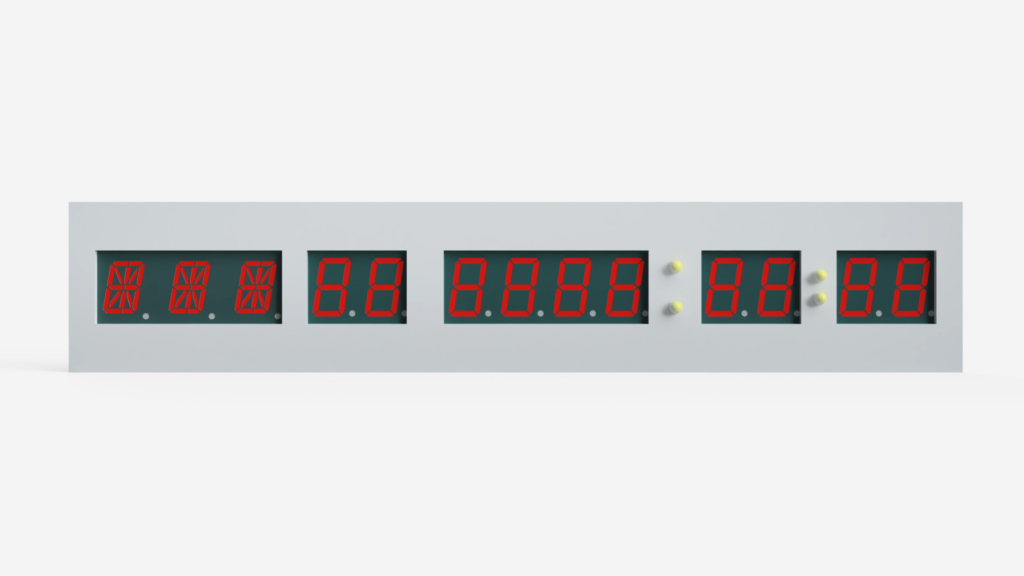
Using these normalized measurements, I created a faceplate in CAD that I think closely resembles the original film’s:

Looking pretty good! I care more about the design than the prop’s execution, so the openings are equally sized and the LEDs are horizontally centered on the display gaps. But I’ll need to mix things up for my own prop.
Shifting Spaces
Since I’m couldn’t find displays that perfectly match the original prop, I’m not going to be able to use the exact dimensions of the original. Here are the displays I’ve chosen in an assembly with that original faceplate:

WOW, that’s actually looks pretty damn close to perfect. There are a few small issues to fix, however.
‘Month’ Opening
I knew this was going to be a problem because of the width of the alphanumeric displays. The corners of the display segments are barely covered by the faceplate (~0.015″ in total), while the ‘Month’ display in the film has a lot of space around it. I’m going to bump out that opening to give the month display a bit of breathing room.
Width Tolerance
With the dimensions from the film, the openings for the seven-segment displays are sized exactly to the width of the displays. In the film the openings hug the digits pretty closely, and I don’t want to attempt +/- 0.005″ precision with my angle grinder work. So I’m going to size-down the width slightly so the PCB doesn’t show through.
Height Resizing
Since all of the LED displays I’m using are slightly smaller than their film counterparts (0.5″ and 0.56″ for the alphanumeric and seven-segment digit heights respectively, compared to the 0.6″ from the film), I’m going to scale the opening heights ever-so slightly. Once again for the display opening tolerance, but also so things look more in proportion.
Reworked Faceplate
Here is my reworked faceplate, using the adjustments from above:

And here is the faceplate on its own:

I took 0.050″ off of the width for every seven-segment opening, which is enough to enclose the display and just barely start cropping the decimal point. This gave me an extra 0.200″ of spacing – 0.130″ of that went to expanding the size of the ‘Month’ display opening, and the remaining 0.070″ went to expanding the edge spacing on either side from 0.215″ to 0.250″. Now the ‘Month’ display is fully visible, and there is slightly more clearance on either side for the PCB in the enclosure.
| Description | Original Measurement (in) | New Measurement (in) | Change (%) |
|---|---|---|---|
| Edge to 'Month' | 0.215 | 0.250 | 16.3 % |
| 'Month' Opening | 1.650 | 1.780 | 7.9 % |
| 'Month' to 'Day' | 0.235 | 0.235 | - |
| 'Day' Opening | 1.000 | 0.950 | 5 % |
| 'Day' to 'Year' | 0.350 | 0.350 | - |
| 'Year' Opening | 2.000 | 1.950 | 2.5 % |
| 'Year' to 'Hour' | 0.500 | 0.500 | - |
| 'Hour' Opening | 1.000 | 0.950 | 5 % |
| 'Minute' to 'Hour' | 0.335 | 0.335 | - |
| 'Minute' Opening | 1.000 | 0.950 | 5 % |
| 'Minute' to Edge | 0.215 | 0.250 | 16.3 % |
For the height I scaled everything down by about 5%, keeping things rounded to 0.005″.
| Description | Original Measurement (in) | New Measurement (in) | Change (%) |
|---|---|---|---|
| Display Opening | 0.740 | 0.700 | 5.4 % |
| 'AM / PM' LEDs | 0.405 | 0.385 | 4.9 % |
| 'Second' LEDs | 0.230 | 0.220 | 4.3 % |
For comparison, here you can swap between both faceplates:
Looking at the two faceplates together makes it seem like these are huge changes, but I honestly don’t think I’d notice unless I had them side-by-side. The whole assembly looks really slick together and I think it’s going to turn out well.
Conclusion
And that’s it! With those few small tweaks, I have a working faceplate for my prop time circuit displays. I’m not going to make the faceplate just yet, but now that I know the LED positions I can start designing the custom display circuit board.
Next up: Making the PCB schematic
Additional Tables
Because it’s useful as a reference, here are two more additional tables: the horizontal centers of each opening, and the horizontal centers of each LED display.
Both tables are measured from the left-most edge of the 8.5″ faceplate.
Display Openings – Horizontal Centers
| Description | Original Faceplate (in) | Project Faceplate (in) |
|---|---|---|
| 'Month' Opening | 1.040 | 1.140 |
| 'Day' Opening | 2.600 | 2.740 |
| 'Year' Opening | 4.450 | 4.540 |
| 'AM / PM' LEDs | 5.700 | 5.765 |
| 'Hour' Opening | 6.450 | 6.490 |
| 'Second' LEDs | 7.1175 | 7.1325 |
| 'Minute' Opening | 7.785 | 7.775 |
LED Displays – Horizontal Positions
| Description | Display Number | Original Faceplate (in) | Project Faceplate (in) |
|---|---|---|---|
| 'Month' #1 | DS1 | ~0.410 | ~0.510 |
| 'Month' #2 | DS2 | 1.040 | 1.140 |
| 'Month' #3 | DS3 | ~1.670 | ~1.770 |
| 'Day' #1 | DS4 | 2.350 | 2.490 |
| 'Day' #2 | DS5 | 2.850 | 2.990 |
| 'Year' #1 | DS6 | 3.700 | 3.790 |
| 'Year' #2 | DS7 | 4.200 | 4.290 |
| 'Year' #3 | DS8 | 4.700 | 4.790 |
| 'Year' #4 | DS9 | 5.200 | 5.290 |
| 'Hour' #1 | DS10 | 6.200 | 6.240 |
| 'Hour' #2 | DS11 | 6.700 | 6.740 |
| 'Day' #1 | DS12 | 7.535 | 7.525 |
| 'Day' #2 | DS13 | 8.035 | 8.025 |
You can derive these from the opening centers easily enough: the displays on either side of the opening’s center plane are horizontally centered at half of their width (horizontal opening coordinate – display width / 2). You can also see that two of the three ‘Month’ displays are approximations because their casing width is in millimeters. The standalone LEDs are positioned exactly on center of their openings, so there’s no reason to repeat the measurements in both tables.
The display numbers are annotated along the X axis (horizontally) from left to right.


2 Comments
Jeff · August 6, 2018 at 12:29 pm
would you be willing to share the CAD file so I could give it to a laser cutting service? thanks!
Dave · August 11, 2018 at 5:33 pm
Hey Jeff!
For a few different reasons, I’m trying to avoid distributing files from the project. All of the dimensions for building your own CAD files for lasercutting, either based on the original or my modifications, should be in the post. Sorry!