With the LED characters in-hand, the next step is to write an embedded program to display integers and strings on the time circuit displays. The goal is to be able to set the characters for each display group based on simple variables, so doing something like displaying the time returned from a real-time clock (RTC) becomes trivial.
Programming Goals
I have a few set goals for how I want the display program to work:
Goal #1: Single Set of Characters
Simply put: I want there to be only one reference array for the character symbols on each type of display (16 and 7-segment). I don’t want to refer to duplicate character sets depending on what I’m referencing, so that characters are consistent throughout.
Goal #2: Single Pathway
In short I want everything to follow a clear and well-defined path for writing characters to the display. I don’t want multiple functions where there could be one (no duplicated code), and I don’t want there to be multiple ways to accomplish the same thing.
Goal #3: Dynamic Assignment
Although I’m building this first and foremost as a replica of the prop from the film, I want to be able to write whatever I want to the display. I have a few ideas for using these displays standalone, and I don’t want something like the ‘Month’ display to be hard-coded to a string set.
All things considered these should be easy-enough to follow, although they are more… guidelines, than actual rules.
Base Functions
Before the characters can be written dynamically, first I need to get them showing on the segmented displays. This is done using some base-level functions which perform the heavy lifting of splitting up data and writing the LED information to the buffer.
Displaying Characters
This is where mapping out the LED segments in-line on the TCD schematic comes to fruition. Because the pins on the HT16K33 are mapped 1:1 with the segments, setting characters is as easy as counting in order whether each segment is on or not and then writing that as binary data. And because each seven-segment display is its own byte, the same LED character can be written to two digits in the same group by a simple bitshift!
After making slight modifications to a few characters based on my research, I loaded the character literals from my segmented ASCII library as arrays into the Arduino’s flash memory. Then I wrote a function to set displays to characters.
The function, writeCharacter(), takes two inputs: the display number (logical, indexed from 0) and a character to show.
Writing characters to the 16-segment displays is a snap:
void tcDisplay::writeCharacter(uint8_t dispNum, char c){
  displayBuffer[dispNum] = pgm_read_word_near(SixteenSegmentASCII + c);
}
Writing characters to the 7-segment displays is slightly more difficult, as it’s done with a bitwise operator as to not disturb the other grouped digit. If writing to the second digit in the group the mask and character are shifted by 8.
First, the buffer for the character being written is cleared with a bitwise ‘AND’ (&). Next, the charaxcter is read and written with a bitwise ‘OR’ (|).
void tcDisplay::writeCharacter(uint8_t dispNum, char c){
  uint8_t bufferN = (dispNum + 3) / 2;

  switch(dispNum & 1){
    case(1): // Odd display #, no shift
      displayBuffer[bufferN] &= 0xFF00;
      displayBuffer[bufferN] |= pgm_read_word_near(SevenSegmentASCII + c) & 0xFF;
      break;
    case(0): // Even display #, shift right by 8
      displayBuffer[bufferN] &= 0x00FF;
      displayBuffer[bufferN] |= (pgm_read_word_near(SevenSegmentASCII + c) & 0xFF) << 8;
      break;
  }
}
This is also complicated by the grouped AM/PM and ‘seconds’ LEDs. I ended up writing two sets of switch cases that alternate between a ‘0x7F’ and a ‘0xFF’ mask depending on the digit range. I tried dynamically setting the mask but it was less efficient and significantly harder to follow. No point in shorter code if it ends up obfuscating things just to make the program slower.
With this function, each segmented display can now show all ASCII characters!
Displaying Strings
The next logical step is to write a function to display text strings, as strings are nothing more than an array of characters.
For this, the string is passed to the function as a character pointer. Characters are assigned to each display in-turn using the character mapping function above. If the parsing loop runs out of displays or reaches the end of the string (null character) the function ends.
void tcDisplay::writeString(const char* s){
  for(uint8_t dispNum = 0; dispNum < 13; dispNum++){
    if (s[dispNum] == 0){ return; } // End of string

    writeCharacter(dispNum, s[dispNum]);
  }
}
There’s no reason to display strings in the project itself (at least not yet), so I’m going to leave this pretty barebones. Although hopefully I can expand it to take care of decimal points so they don’t take an entire display, and perhaps do something about spaces as well. It might also be wise to rewrite the function to be able to work with digit sets rather than the whole display.
Setting Numbers
Strings and characters are one thing, but numbers are another. While each digit (character) in a string is stored separately, numbers need to be converted from base 2 back into base 10.
void tcDisplay::writeNumber(uint32_t n, uint8_t nDisp, uint8_t sDisp){
  if(sDisp + nDisp > 13) { return; }

  for(int i = 1; i <= nDisp; i++){
    writeCharacter(sDisp + nDisp - i, (n % 10) + 48);
    n /= 10;
  }
}
The ‘writeNumber’ function takes three inputs: the number to be written, the number of displays to write to, and the display to start on. Modulo 10 gives the number for the last base 10 digit, and the input number is divided by ten to push the next digit forward. This continues until all indicated displays are written.
The beauty of this is that the size of the number doesn’t matter, as it writes from least-significant digit to most. Once it runs out of numbers it writes ‘0’ to the remaining digits, same as the time circuits in the film.
Each 0-9 number is passed as a character (number + ASCII offset of 48) to the character function to show the symbol on the segmented displays.
This could also be upgraded to support negative numbers (adding a ‘-‘ sign) and floats. But that isn’t necessary for the prop’s functionality, so it’s work for another time.
Setting Standalone LEDs
Lastly there are the four standalone LEDs, used for ‘AM / PM’ and ‘seconds’. Since both the ‘AM / PM’ and ‘seconds’ sets share the same ROW pins on different COMs, I can re-use one set of code and just feed the function a different buffer number.
void tcDisplay::writeStandalone(uint8_t bufferN, uint8_t n){
  static const byte ledIndex = 0x80;

  if(bufferN < 3 || bufferN > 4 || n >= 4) { return; }

  uint16_t ledMask;

  displayBuffer[bufferN] &= ((~ledIndex & 0xFF) << 8) | (~ledIndex & 0xFF); // Clear previous

  switch(n){
    case(0): // All Off
      ledMask = 0x00;
      break;
    case(1): // All On
      ledMask = ledIndex << 8 | ledIndex;
      break;
    case(2): // LED 1
      ledMask = ledIndex;
      break;
    case(3): // LED 2
      ledMask = ledIndex << 8;
      break;
  }

  displayBuffer[bufferN] |= ledMask;
}
The function clears the two LED states and then sets them based on the passed variable.
Readout-Specific Functions
With the base-level functions in place, next-up are the readout-specific functions. These are abstractions of the base-level functions that limit their scope to specific readouts without the user needing to figure-out the exact indices and ranges.
Month
The ‘Month’ function takes an integer from 1 – 12 as a parameter and then writes the corresponding abbreviation to the alphanumeric displays. It reads directly from a two-dimensional array in flash that holds the abbreviations.
void tcDisplay::writeMonth(uint8_t mmm){
  if(mmm < 1 || mmm > 12){ return; }

  for(int i = 0; i < 3; i ++){
    writeCharacter(i, (char) pgm_read_byte_near(&MonthAbbr[mmm - 1][i]));
  }
}
This is more-or-less just a ‘number to string’ converter, but there’s little reason to call the writeString() function if I can assign the characters with a short for() loop.
Day, Year, Hour, Minute
For simplicity each 7-segment display group gets its own function that passes its display indices along to the writeNumber() function. This way it’s easy to write a number to a digit set without overwriting another.
‘Day’, ‘Hour’, and ‘Minute’ each get a variation of the same one-line function:
void tcDisplay::writeDay(uint16_t dd){
  writeNumber(dd, 2, 3);
}
The only number that changes is the ‘starting’ display (3, 9, and 11, respectively). ‘Year’ is similar, with the obvious expansion of its ‘nDisp’ value to 4 displays.
I’m still considering whether I want the two-digit displays to ‘max out’ at 99 if it receives a larger number. Although there are times when you want to display only the last two digits of a large set. Something to think about.
AM / PM
For the AM / PM function I set up an enumeration. This way the user can select “AM” or “PM” when calling the function to turn on the respective LED.
enum AMPM_t {Off, On, AM, PM};

void tcDisplay::writeAMPM(AMPM_t s){
  writeStandalone(3, s);
}
The beauty of using an enumeration here is that it’s still passed to the writeStandalone() function as an integer. By setting the “AM” and “PM” positions as 2 and 3 in the enumeration list, respectively, I can keep positions 0 and 1 for “Off” and “On” while still being able to set each LED separately.
Seconds
The function to drive the ‘seconds’ LEDs takes an integer input and toggles the LEDs based on whether the input is even or odd. By setting the LEDs ‘on’ for odd inputs, boolean inputs still behave as expected.
void tcDisplay::writeSeconds(uint8_t ss){
  if(ss & 1){
    writeStandalone(4, 1);
  }
  else{
    writeStandalone(4, 0);
  }
}
It occurred to me as I was writing this that I don’t know if the ‘seconds’ lights in the movie blink on odd or even seconds. Perhaps that’s something to look into.
Demonstrations
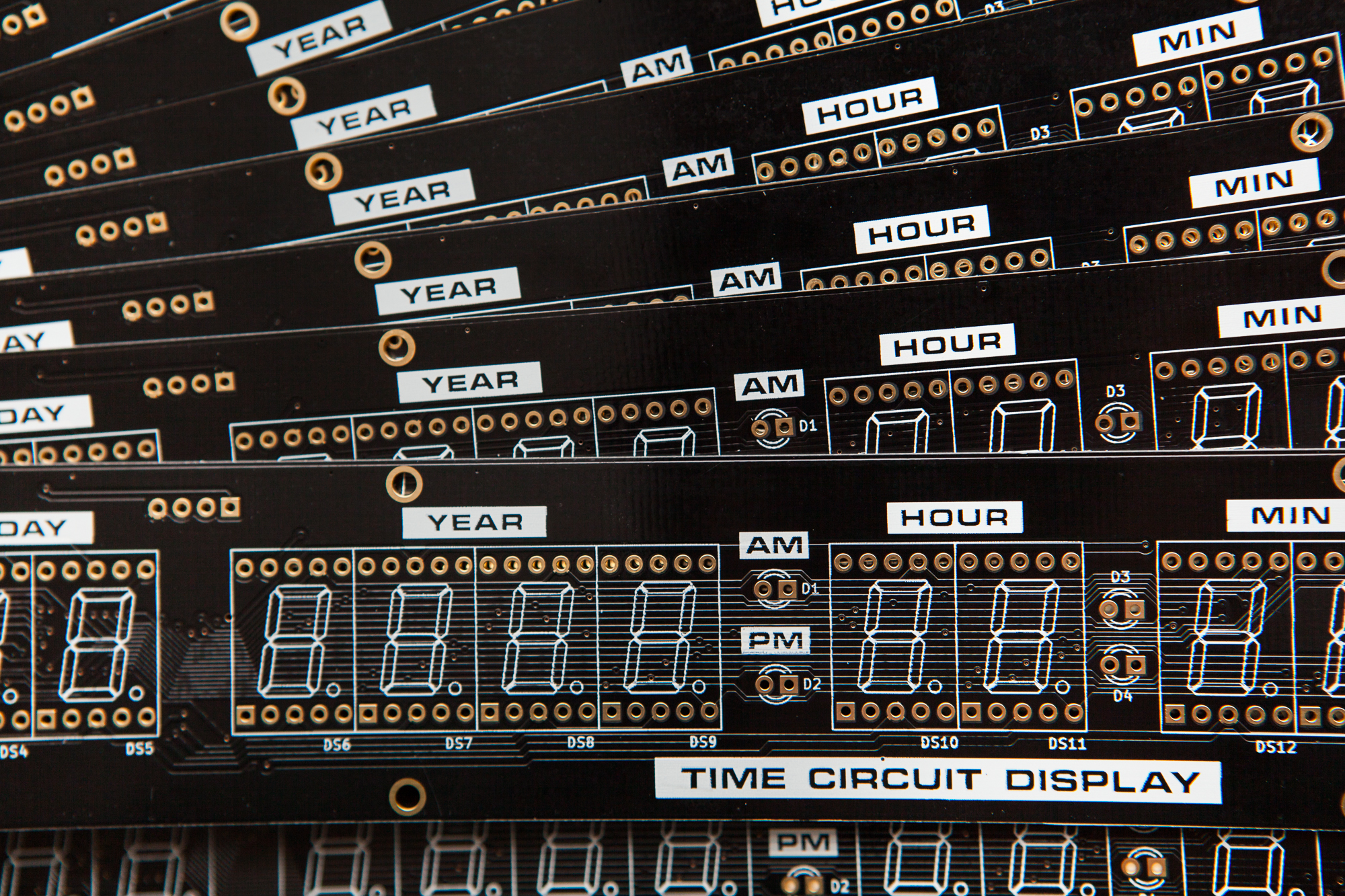
The display circuit boards are still in the mail somewhere, so the demonstrations will have to be on the prototype version.
Time Circuit
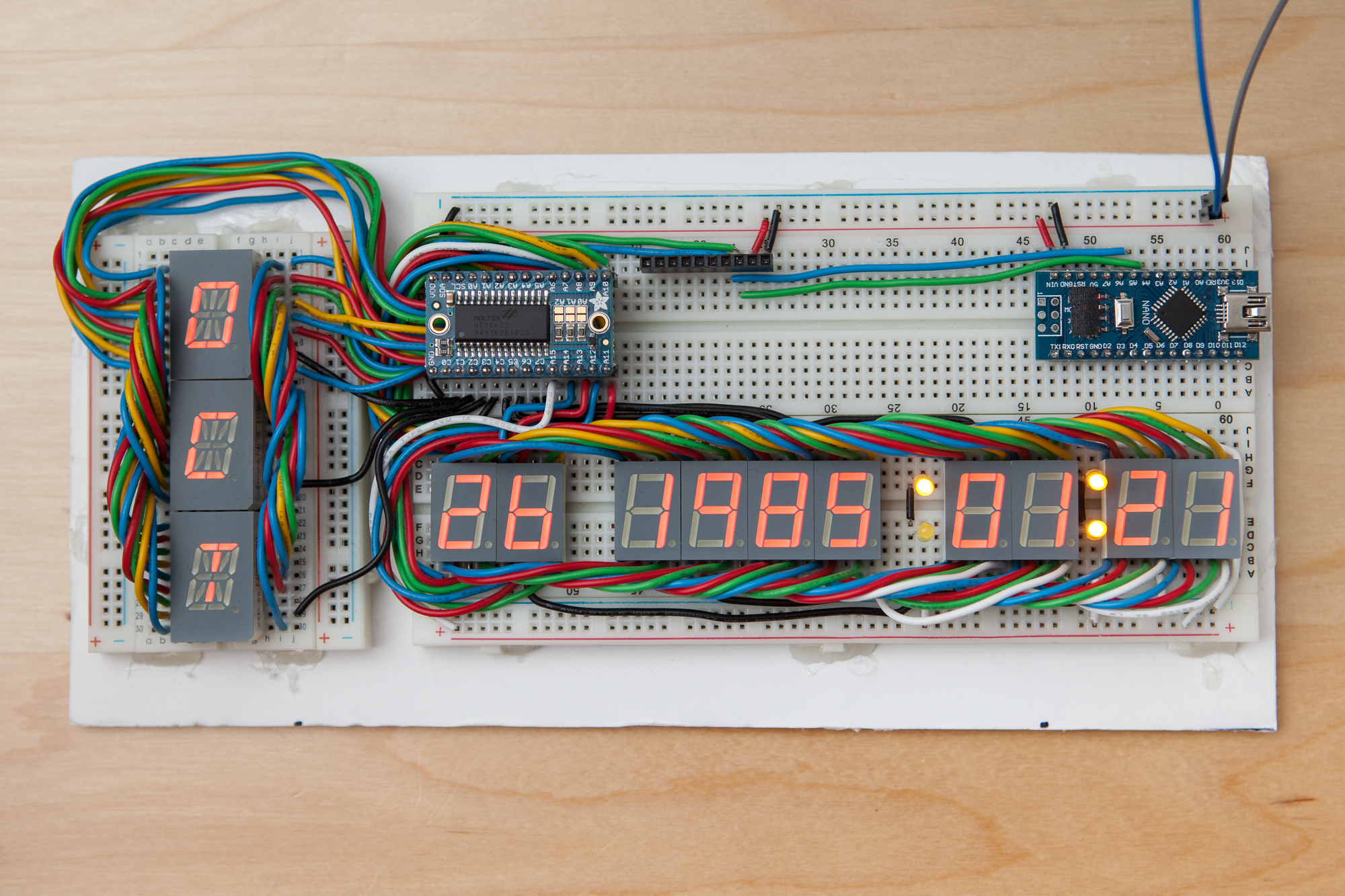
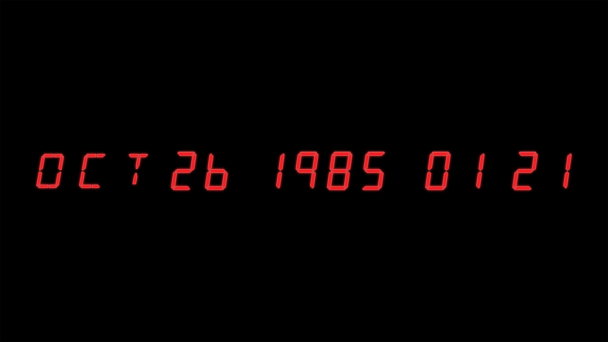
The world’s first time traveler.
String
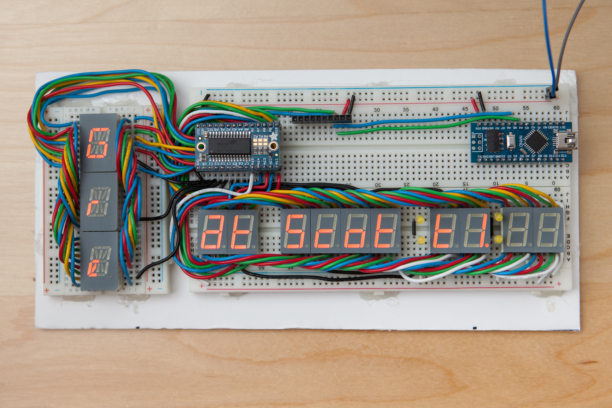
This is heavy…
Numbers
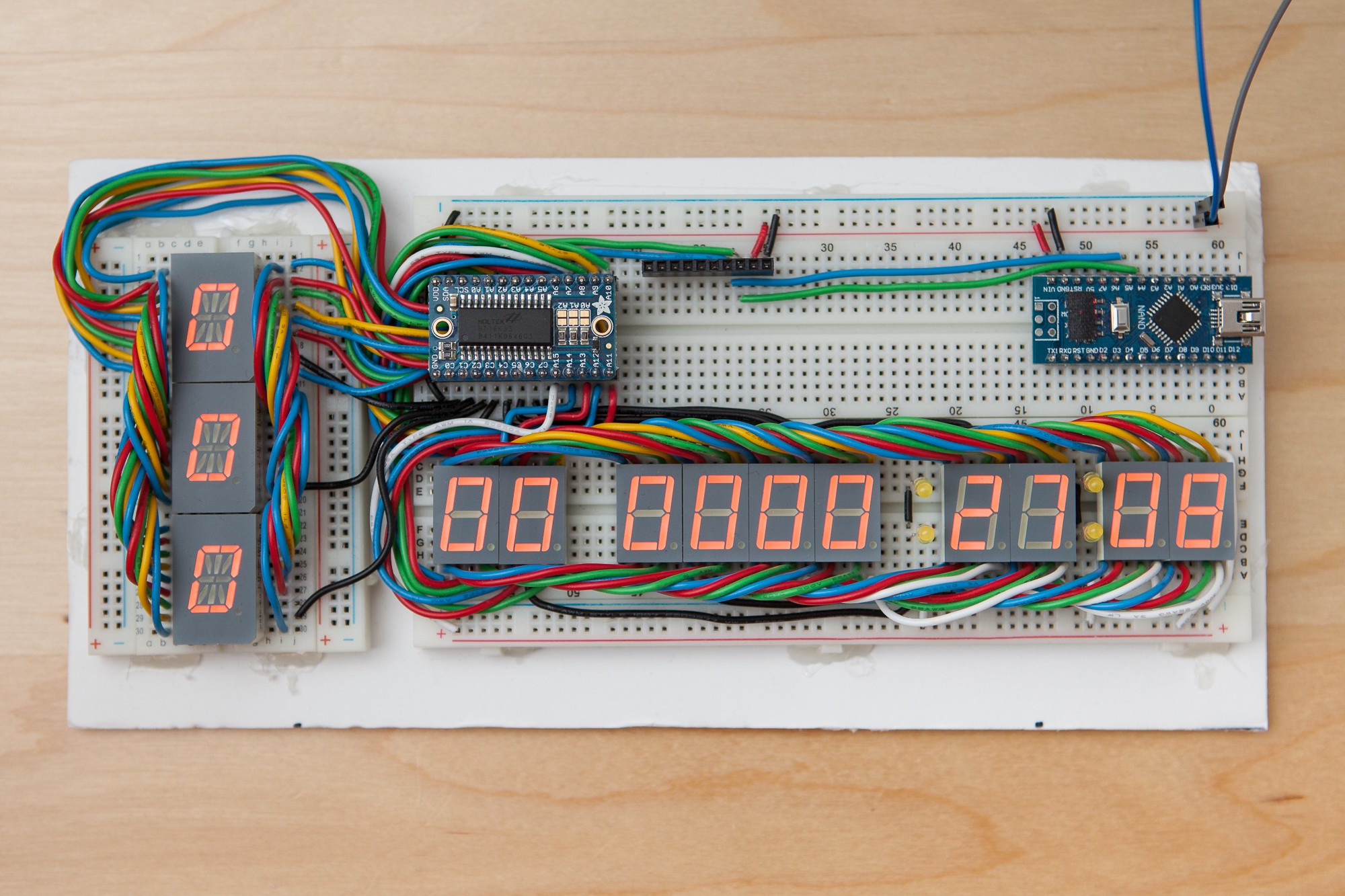
Counting up from 0
Conclusion
This should be all of the programming that’s needed to get the displays up and running, although I still have more ideas for how to improve it. Just off the top of my head:
- Support floats and negative integers
- Add per-display functions for strings
- Support merging decimal characters
- Expand ‘clear’ function to work with ranges and individual digits
None of that is particularly hard, but it’s tedious and rather unnecessary for the time being. I have a feeling that I’m going to be tweaking the programming somewhat continuously until the project is declared “done”.
Although the basic display programming is more-or-less complete, there’s plenty more programming to be done for the time-keeping and keypad inputs. Still more to come!
Next-up: Assembling the time circuit display PCB (hopefully!)
8 Comments
Grey Area · April 24, 2018 at 2:18 pm
Thanks for this! I’m trying to achieve something much simpler, but starting from almost zero knowledge…your test sketch for the HT16K33 at least proved I wired all my LCDs correctly…now I just need to get them to read what I want (output from analog potentiometers) …
…should onyl take me amonth or so I guess (slow learner!)
Thanks again!
Tommy · December 17, 2018 at 5:44 pm
Can I use dual 7 segment in cascade??
Fioulmaster · June 17, 2020 at 10:23 am
Hello, I have a question:
HT16K33 driver have 8 com lines but you have 13 digits to control.
How can you drive all digits?
Dave · June 17, 2020 at 10:27 am
Take a look at the schematic. The HT16K33 has 16 “ROW” pins for each common, and the 7-segment displays require 8 pins each. 5 of the common lines control 2 7-segment displays each.
Fioulmaster · June 17, 2020 at 11:29 am
Ok. I have not saw the schematic.
I understand better. Thanks. 👍🏻
Pieter · July 9, 2019 at 2:21 am
Good day. Thank you for your articles. Any chance of getting the source code?
Kind regards
Pieter
Dave · July 9, 2019 at 12:55 pm
Hi Pieter,
The source code, such as it is, is all in the article. I never did get around to finishing this project so there is no ‘source code’ so to speak. Just the methods I came up with here for parsing out data for the displays.
Rubens · January 16, 2024 at 2:15 pm
I am using 14 segment 3 digit displays instead of 1 digit 16 segment how do I connect those up to make the same code work? Also did u make some sort of library?