I have no formal education as an electrical engineer, so one of my first steps for the time circuits project is figuring out how to drive the large number of LED segments that make up the three time circuit displays.
Counting Segments
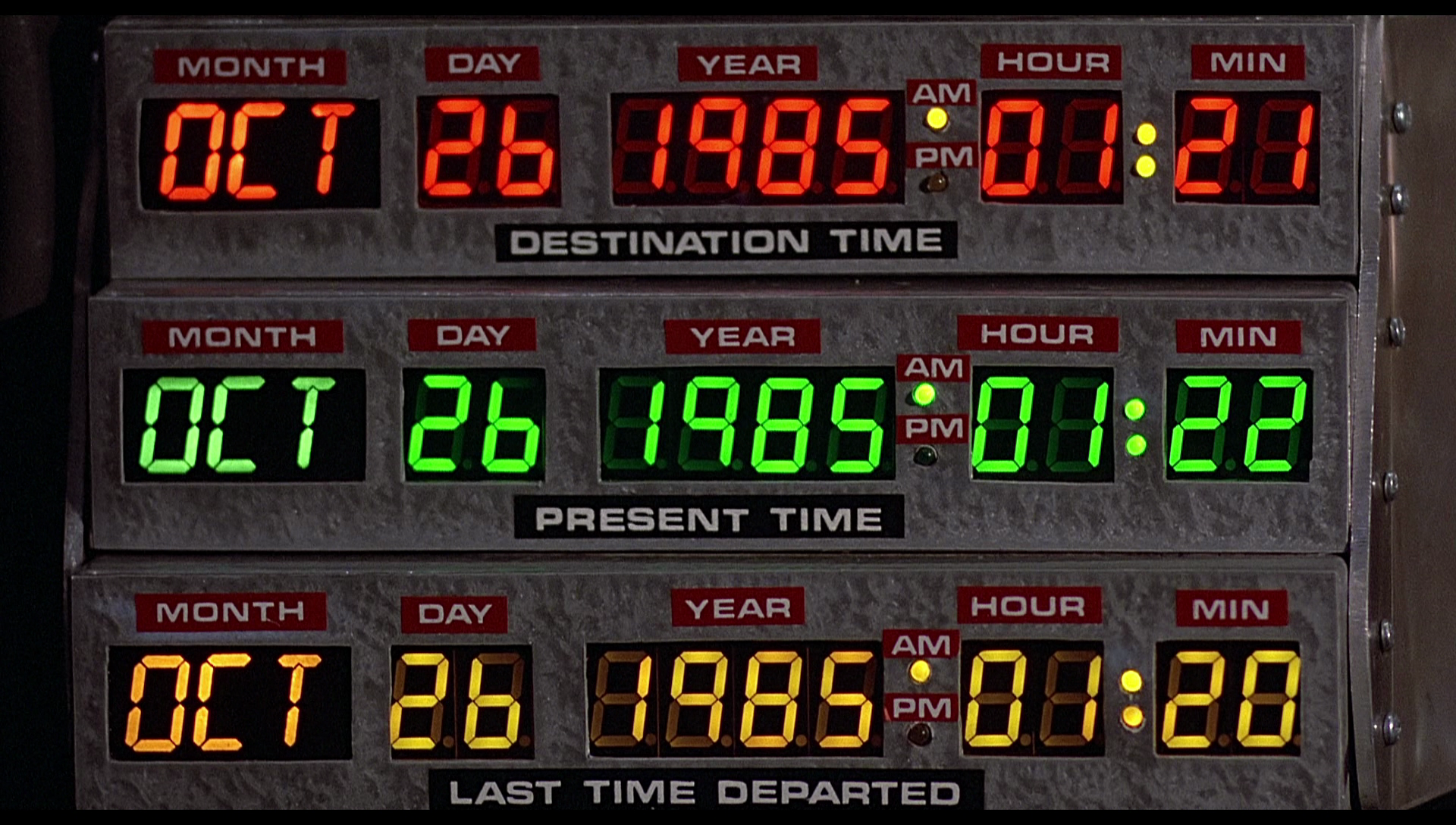
The time circuit displays, as seen in the first film
The time circuits are made up of three identical displays, each showing a different date and time. Each display has the following components:
- Month: 3 digit, 14 segment alphanumeric display.
- Day: 2 digit 7-segment display.
- Year: 4 digit 7-segment display.
- AM / PM: 2 LEDs that alternate, depending on whether the 12-hour time is AM or PM.
- Hour: 2 digit 7-segment display.
- Second: 2 LEDs that blink together every other second.
- Minute: 2 digit 7-segment display.
Ignoring the decimals, that’s a whopping 116 LEDs per display, or 348 individual LEDs in total. That’s a lot of LEDs…
HT16K33
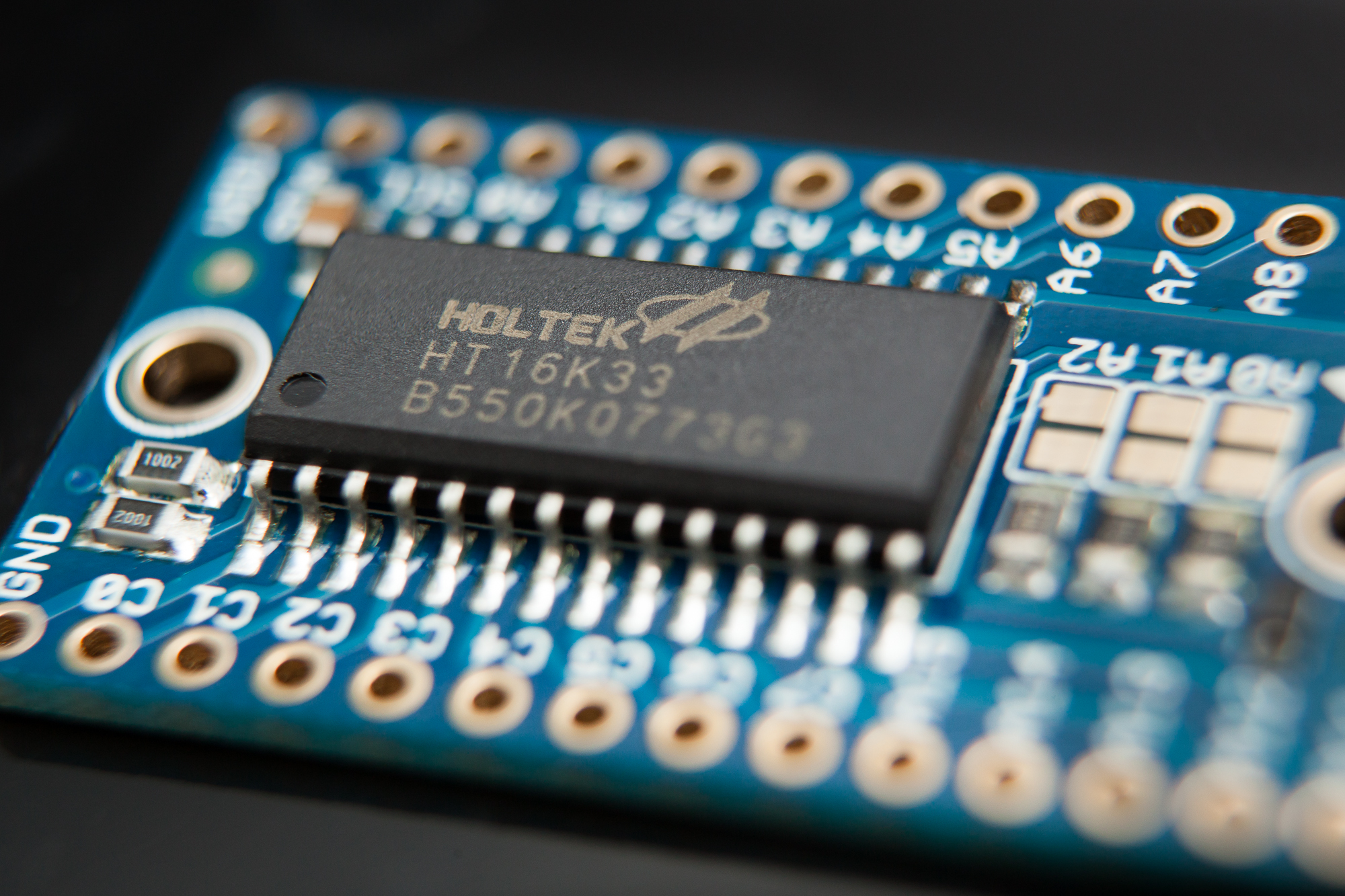
Enter the Holtek HT16K33, the magical little integrated circuit that should make driving these displays a piece of cake. Instead of 348 control wires, we only need two.
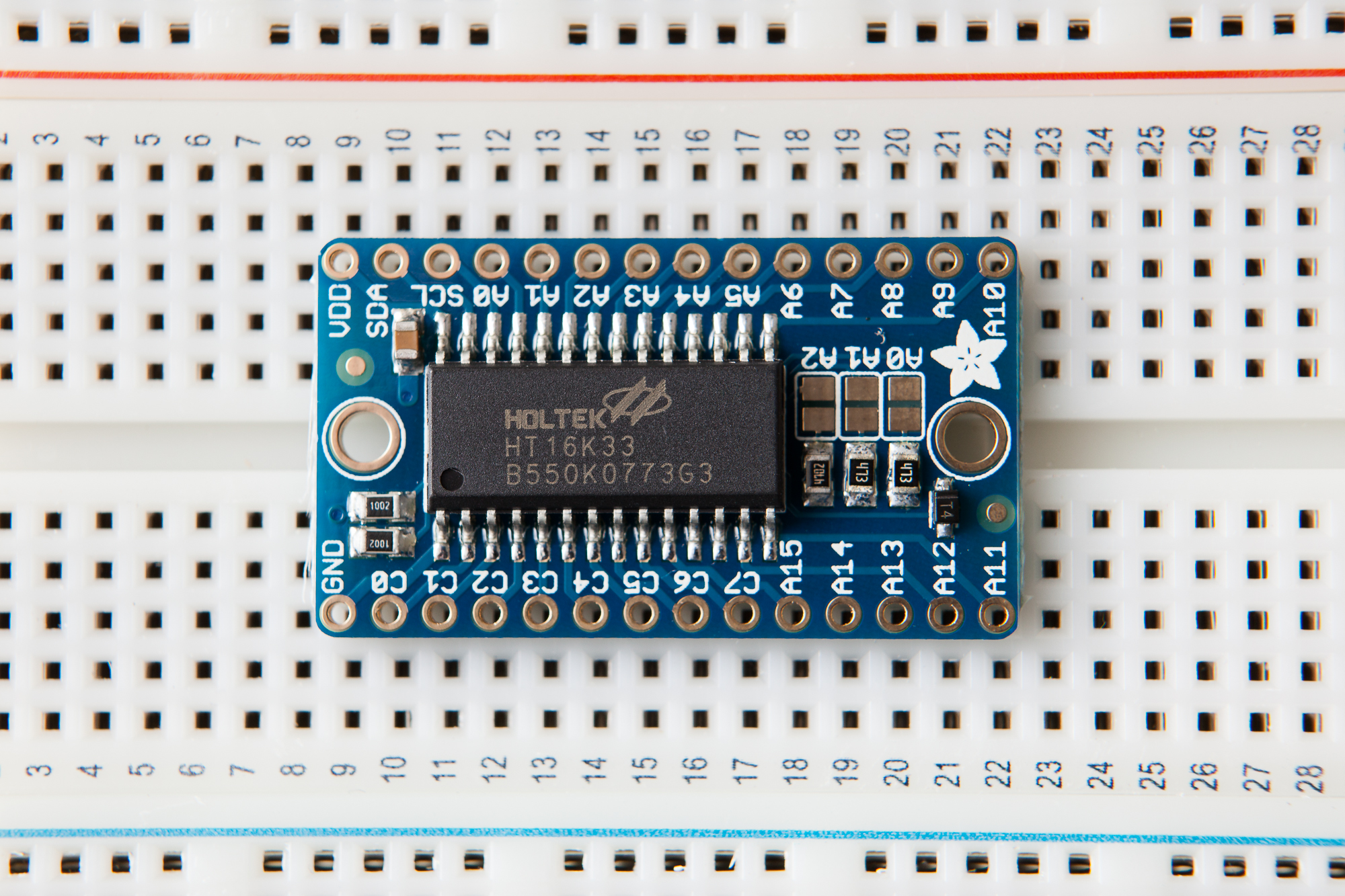
Adafruit’s HT16K33 breakout
The HT16K33 is a 16 x 8 LED matrix driver that can be controlled by the I2C bus. It can directly drive and control 128 individual LEDs, which makes it perfect for the 116 LEDs needed for each time circuit display.
Each of the 16 ‘segment’ pins can provide ~25 mA of power, and is sunk by one of the 8 ‘common’ ground pins. This limits us to using common cathode displays.
Multiplexing
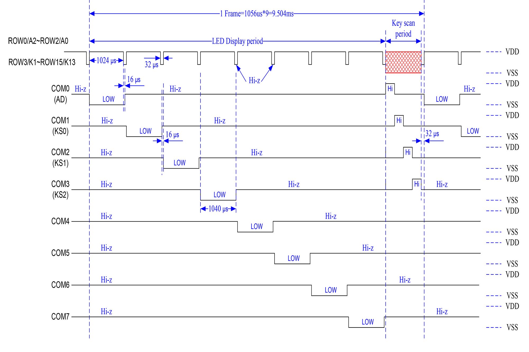
Multiplexing diagram, taken from the HT16K33 datasheet
To drive so many LEDs with so few pins, the HT16K33 uses a technique called ‘multiplexing’. Multiplexing takes advantage of persistence of vision, where each group of LEDs is only illuminated for a very short period of time. The other benefit of hardware multiplexing is that you don’t need resistors on the LEDs; the duty cycle is low enough that the added heat isn’t an issue.
I2C
Because the HT16K33 is controlled by I2C, all three displays will only require a total of two control wires going to the microcontroller: clock and data (SCL and SDA). We can prepare the binary data for each display and use the addressable bus to control which LEDs are enabled at any given time.
Package
The HT16K33 is available in three packages: 20 SOP-A, 24 SOP-A, and 28 SOP-A. I’ll need to use the 28 pin package to cover all of the segments.
While it would be easier to use an IC that came in a larger DIP package with a socket, the SOP package comes with the territory. I can either give reflow soldering a try or brush up on my small parts soldering skills.
I could desolder the I2C pullups and use the Adafruit breakout boards, but where is the fun in that?
Tradeoffs
Despite all of the benefits of using an I2C multiplexing controller, there are a few tradeoffs.
For starters, multiplexing is great for human eyes but doesn’t work for applications where the display needs to be read in a short period of time (such as high speed filming / photography). With the HT16K33, a single frame of all LEDs takes 9.504 ms to display, which will cause issues at shutter speeds of ~ 1/125 and faster.
Multiplexing also has variable power requirements, as the same number of segments are usually not lit for each digit. These varying cyclical power requirements can induce ripple currents in the power supply, although that’s an issue we can deal with later if need be.
I2C, useful as it is, also has a few issues – notably bus speed, limited addresses, and short cabling lengths. None of these should cause problems for this project, however (famous last words!).
Another important note about the H16K33 in particular is that it is produced by Holtek Semiconductor Inc., which is based in Taiwan and does not distribute to major US electrical distributors such as Mouser and Digikey. This might make buying a small number of these chips difficult.
Shift Registers?
I can hear a few people in the back murmuring “why not use shift registers?” A few reasons:
Complexity
Instead of the single matrix chip, I would need a shift register output for each LED (i.e. multiple registers) and a resistor for each LED, which is many more parts and many more things to solder. One IC means fewer parts, fewer things to solder, fewer traces to route, and fewer things that can break.
Software Multiplexing
I can get around this issue somewhat by using registers for a multiplexing / matrix setup, but that would require software multiplexing. And in the event that the software fails for any reason the LED displays would be damaged. Better to stick with a hardware solution, if possible.
I2C
An array of shift registers wouldn’t work using I2C. I know that sounds like a minor issue, but there is a draw to being able to talk to each display separately in exactly the same way. I2C also allows me to chain many displays together, say if I wanted to create a wall-sized time circuit display at some point down the road.
Proof of Concept
My impatience got the better of me, and I wanted to see how a rough prototype would work before I could source all of the ‘correct’ LED displays.
Adafruit sells their own breakout board for the HT16K33, so I purchased one along with a few inexpensive LED displays they had in stock, and wired the setup to an Arduino Nano and a DS1307 real-time clock.
After a bit of basic programming, I can now present to you the ‘Time Circuits Prototype’ version 0.0!
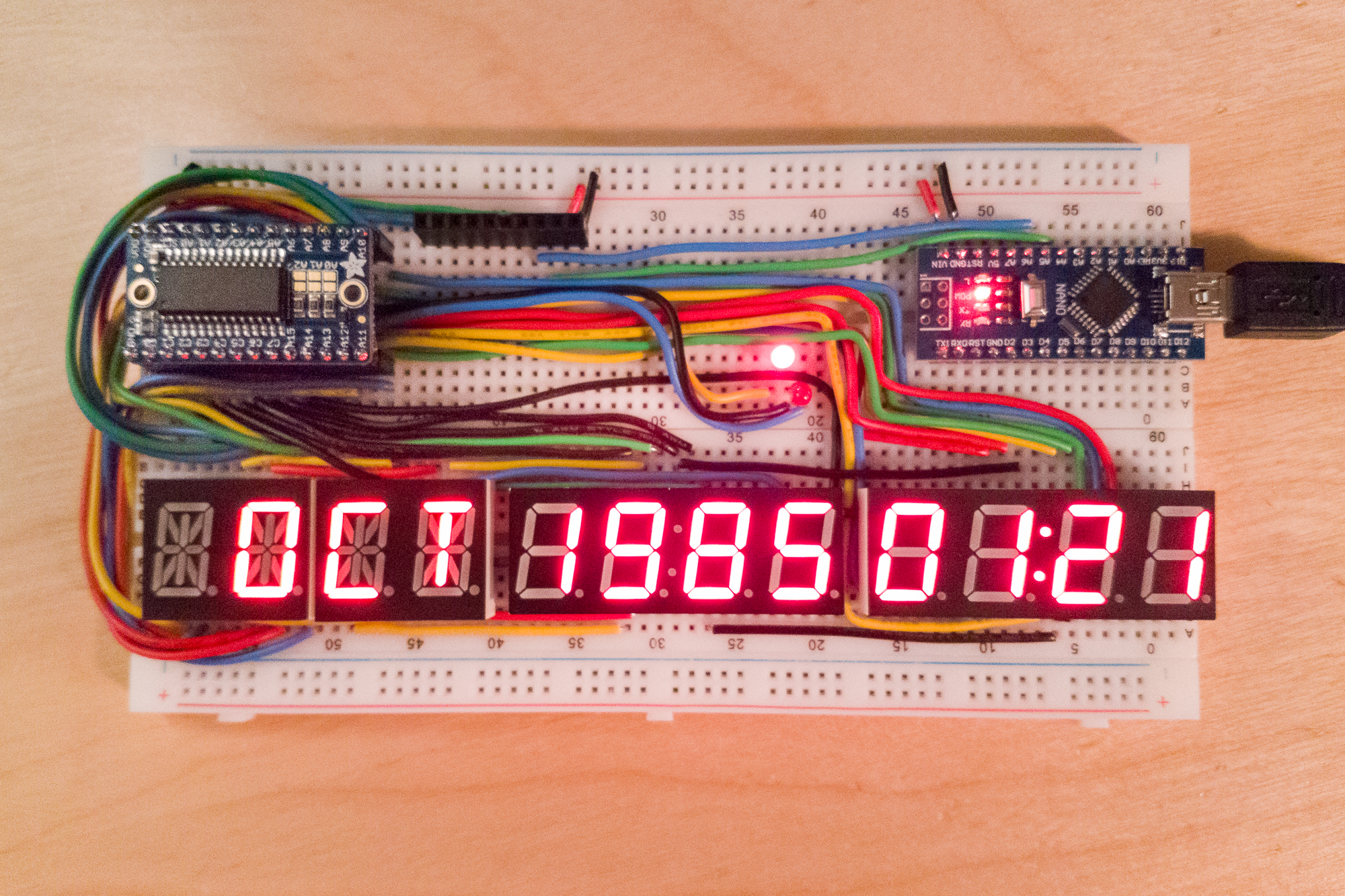
Ain’t she a beaut’! I used two large breadboards snapped together and wired everything with 22 AWG solid core wire. The wiring was a pain, but by hiding some wires underneath each display and using stackable female headers to raise up the breakout PCBs I got everything onto the two boards. The DS1307 wiring is there, but it’s not included in that photo of the static time.
The breadboards are too small to include all of the TCD digits, but I can switch between displaying the alphanumeric month and displaying month / day in decimal for testing. The prototype’s wiring layout isn’t exactly the same as it will be for the PCB because of the multiplexed four-digit displays, but it’s close enough to create the font patterns and do some of the initial programming.
Mostly it’s just a cool proof of concept.
Conclusion
I’m hoping that the HT16K33 chip will work for this project, as it will make dealing with the LED displays much easier. The proof of concept is a good first step, although I’d like to test with a full breadboarded complement of LEDs before I start PCB design.

6 Comments
Tommy · March 10, 2019 at 7:28 pm
Dave:
Have you pcb time circuits black pcb för jlcpcb??
Don · February 25, 2021 at 7:07 am
Mr. Madison, I have purchased these HT16K33 directly form china on ebay, I have a few 8x*8 Led matrix that are Common Anode that is a problem for the HT16K33 since they are for Common Cathode. Is there a way you can use the Common Anode with ULN2981a or some mosfets that can drive a common anode?
Tommy · March 10, 2019 at 7:31 pm
Sorry for my misspelling:
Dave:
Have you pcb time circuits black pcb for jlcpcb??
plateshutoverlock · July 17, 2019 at 1:40 am
The original time circuit panel actually used slides and a light bulb for the month indicator, instead of 14 segment digits. If you watch the various months indicated in the films closely, you can see that some of the segments do not correspond with how a “starburst” display is laid out, The month ‘digits’ also don’t have the light bleed into the other segments like the rest of the display has.
This is actually a pet peeve of mine as I’ve seen this error in other films, and even fonts that are supposed to simulate a 14 segment display Yes, I know it’s very pointless for me to be focused on such a minor detail, but being an electronics and computer nerd something like this sticks out like a sore thumb.
Craig Apsey · October 31, 2020 at 4:53 pm
do you have a circuit diagram for this, i’m trying to run 4 x 4digit 7-segment displays with a ht16k33 and I’m struggling a little
Dave · October 31, 2020 at 8:33 pm
You can find the schematic here: https://www.partsnotincluded.com/time-circuit-display-matrix-schematic/