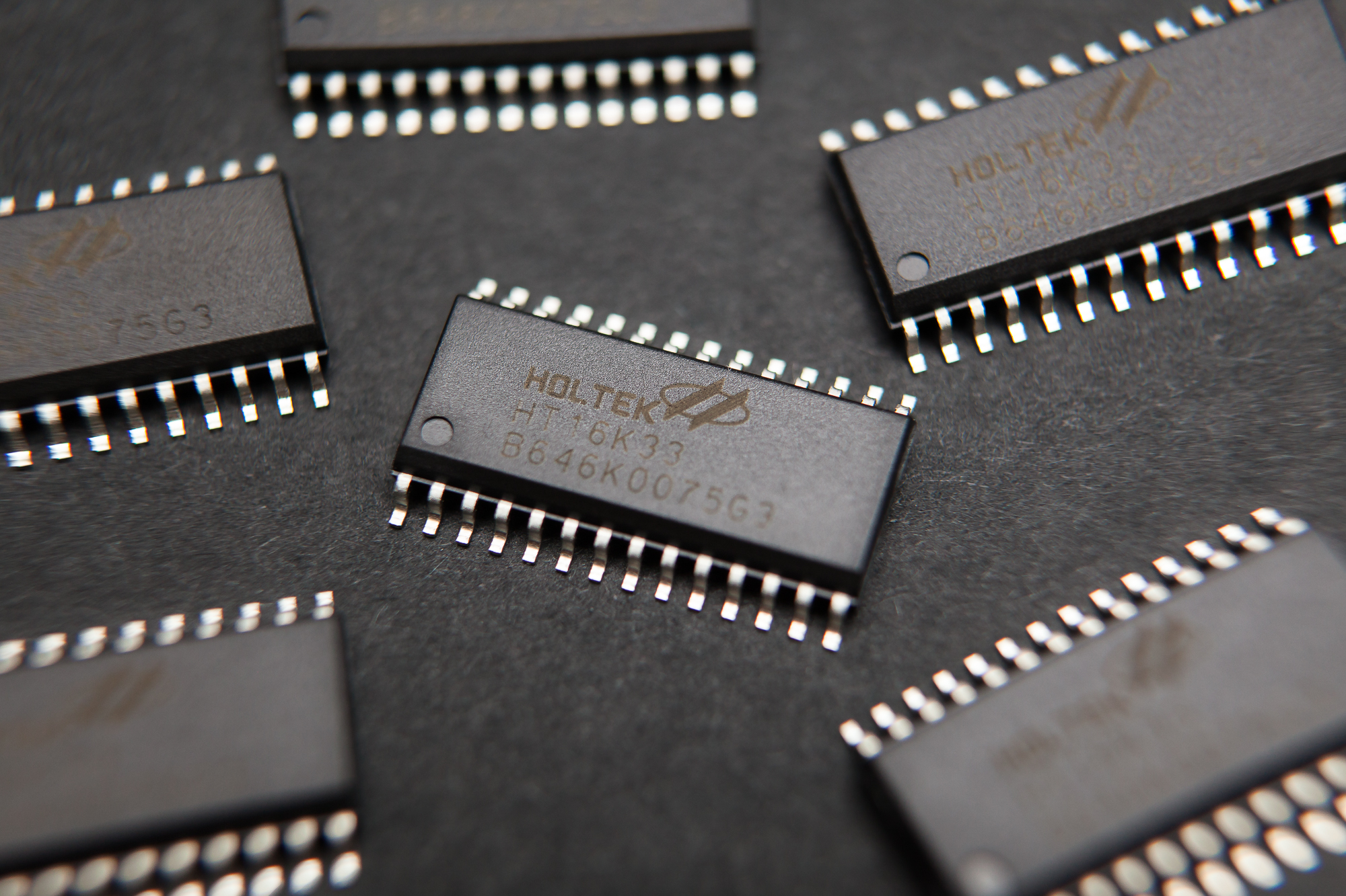
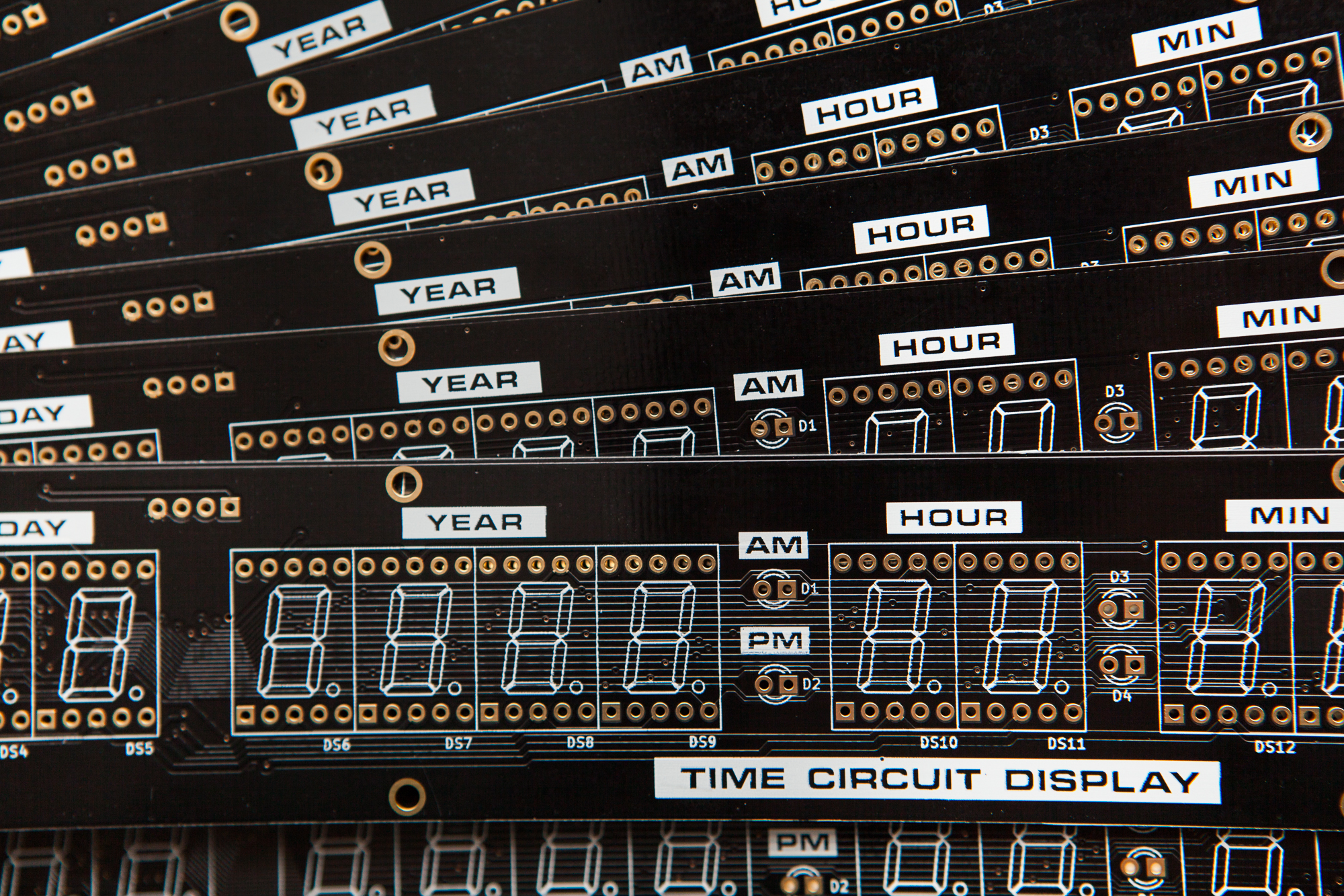
Now that all of the time circuit display electronics are in the mail it’s time to talk about programming the display. This starts with learning how to control LEDs with the Holtek HT16K33 integrated circuit (IC), which I’m using as the display’s matrix driver.
Although I’m writing this post as part of a series on creating my own version of the Back to the Future time circuits, this is a powerful little integrated circuit that can be useful for a number of DIY projects involving LEDs. You can find some more generalized information about the HT16K33 in my other post here.
All of this information below is derived from the Holtek datasheet, which you can find hosted at Adafruit. I’m referencing Rev. 1.10, which is dated May 16, 2011.
HT16K33 Setup
Before sending any commands to the HT16K33 the hardware side of the circuit needs to be set up properly.
Connections
The HT16K33 needs to be connected to a 5V DC power supply. Current requirements increase depending on how many segments are lit, but the IC and matrix shouldn’t draw more than 0.5 A with all segments enabled.
Each display receives its data over the bidirectional inter-integrated circuit (I2C) bus. The bus has two wires: serial data (SDA) and serial clock (SCL). At some point in the schematic these need to be pulled to logical high (5V) through pull-up resistors. All of the HT16K33 displays need to be on the same bus as the controller.
On my time circuit display (TCD) prototype I’m using Adafruit’s HT16K33 breakout board. Like the dedicated TCD circuit board, the breakout board has pull-up resistors for the I2C lines and a decoupling capacitor for the IC. These are a must for the integrated circuit to work properly.
I2C Address Settings
The I2C bus is addressable, which allows a large number of devices to communicate using only two wires. With 7-bit addresses, I could add a total of 128 different devices to the same bus.
Page 26 of the datasheet talks about setting addresses for the HT16K33. The HT16K33 uses a 7-bit address, with the four most significant bits (MSB) set to ‘1110’ (0x70 in hexadecimal, 112 in decimal). This is the ‘default’ address for the chip if no jumpers are set.
Note: The hexadecimal value is a little misleading, as the read/write bit follows the address rather than precedes it. If we’re talking about the entire byte including the r/w bit the first hex character is ‘E’ rather than ‘7’. However for a 7-bit address the constant 4 bits are spread between nybbles, which changes the hex value. C’est la vie.
The remaining three address bits are either ‘0’ or user-configurable depending on the package. I’m using the 28-pin package for the time circuit displays, which allows me to change all three remaining address bits. This means I can use a total of 8 HT16K33 chips on the same bus (23) without using a multiplexer, although I only need three for this project.
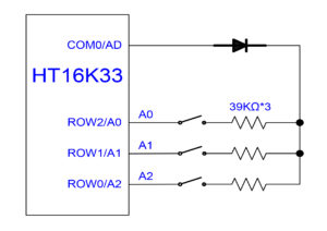
The address bits are set in hardware by wiring 39K resistors in-line with a diode to connect the COM0 pin with either the ROW2 (A0), ROW1 (A1), or ROW0 (A2) pins. Each bridged connection sets its respective bit to ‘1’, while a floating connection sets the bit to ‘0’. On the TCD circuit boards these connections are exposed as jumper pads.
I know it doesn’t particularly matter once it’s stored in the code, but it makes sense to me to set the addresses in a logical order. I’m going to set them increasing from top to bottom, which follows Doc’s little speech when he’s describing the time circuits for the first time:
This readout tells you where you’re going. This one tells you where you are. This one tells you where you were.
As such, the addresses are as follows:
| Display | I2C Address (Hex) | I2C Address (Dec) | I2C Address (Bin) |
|---|---|---|---|
| Destination Time | 0x71 | 113 | 0b1110001 |
| Present Time | 0x72 | 114 | 0b1110010 |
| Last Time Departed | 0x74 | 116 | 0b1110100 |
The first display has its address bits floating, while the second and third have just one jumper soldered on each.
Updated 2017-10-10: I ended up soldering the jumpers for all three displays – A0 through A2, top to bottom. The logic is that I may end up using another HT16K33 somewhere else in the circuit and I could avoid the address resistors / diode altogether. The display boards already have the hardware for changing the addresses, so it makes sense to take advantage of that capability while I can. I have updated the table above accordingly.
I2C Commands for the HT16K33
With the address in-hand, the next step is to send some data over the bus to the integrated circuit. After sending the 7-bit address with an appended ‘write’ bit (0) the HT16K33 will take read control of the bus. The next byte it receives will be a command code.
Each command byte is split into two parts of 4 bits each, called a ‘nybble‘. The first nybble is the command, while the second nybble is the setting.
Note: If you can’t take a byte, you can at least take a nybble. Get it? Who ever said programmers weren’t clever.
Start Oscillation
The first command is the one that turns on the chip’s internal oscillator. This wakes the chip from standby and starts the LED multiplexing.

The command nybble is ‘0b0010’ (0x2). The setting nybble can either be ‘0’ or ‘1’ to toggle the oscillator’s state.
Sending LED Data
With the oscillator enabled I can start sending LED data. The command for this sets the position of the RAM address pointer, and subsequent bytes are the LED data itself.

The command nybble for setting the LED states is ‘0b0000’ (0x0). The setting nybble is the pointer’s RAM address. There are 16 addresses, with each bit corresponding to an LED state (16 addresses * 8 bits per byte = 16 rows * 8 columns). When the address pointer reaches the end of the block it returns to the beginning.
After the command byte, each successive byte sent on the bus will set an LED block state. This means that the command byte and 16 data bytes will set all LED states.
Dimming
After enabling some LEDs, the dimming function allows you to dim the displaying by lowering the pulse width of each ‘ROW’ pin. The dimming function is adjustable with 16 steps (24).
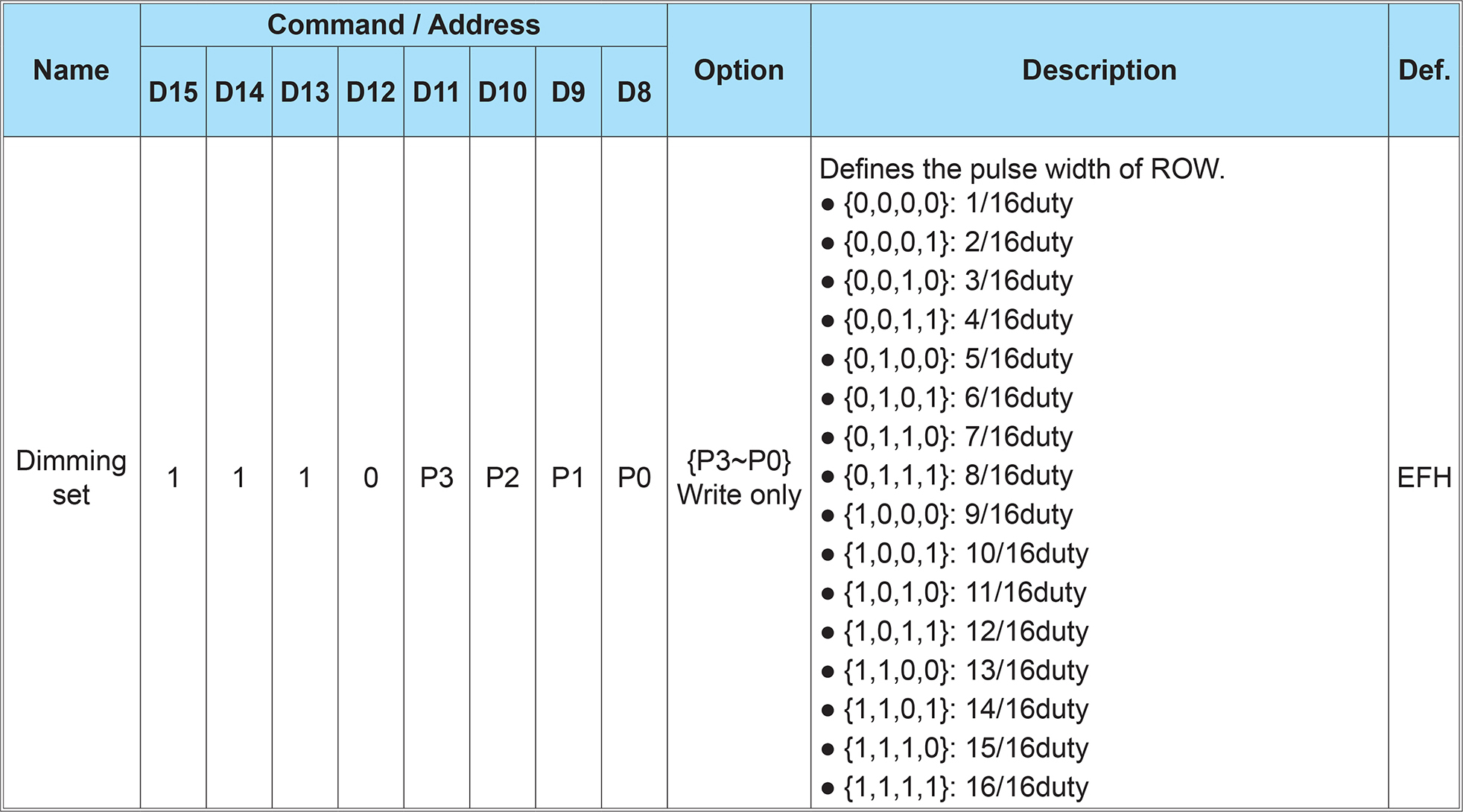
The command nybble for dimming is ‘0b1110’ (0xE). The setting nybble sets the duty cycle from 1 – 16. A setting of ‘0’ is 1/16th duty, while a setting of ’15’ is 16/16 duty.
Blinking and Blanking
The HT16K33 also includes an automatic blinking function with three levels: 2 Hz, 1 Hz, and 0.5 Hz. This command is combined with a blanking feature that turns off the display without turning off the chip’s oscillator or clearing the LED matrix data.

The command nybble for both of these is ‘0b1000’ (0x8). The LSB of the setting nybble sets the display state (off / on) while the second and third bits set the blinking level (0 = off, 4 = 0.5 hz).
There are a few other available commands but they’re only for the chip’s keyscanning operations and they aren’t relevant for the LED displays.
I2C and Arduino
For prototyping I’m using an Arduino Nano as my controller. The Arduino IDE has a built-in library for handling I2C communication called Wire.
After calling Wire.begin() to start the I2C communication, each request over the bus follows the same format:
- Wire.beginTransmission(address) will start a queue for communicating with a slave device at a specific address.
- Wire.write() will queue a byte for transfer.
- Wire.endTransmission() will transmit the bytes queued with
writeand end the communication with the slave device.
With an Arduino, the Wire library is all that’s needed for communicating with the HT16K33.
HT16K33 Arduino Demo
I put together a quick demo sketch using the commands I described above. This sketch initializes the HT16K33, turns on all LEDs sequentially, and then shows off the blinking, blanking, and brightness commands.
#include <Wire.h>

const uint8_t addr = 0x70; // HT16K33 default address
uint16_t displayBuffer[8];

void setup() {
	Wire.begin();

	Wire.beginTransmission(addr);
	Wire.write(0x20 | 1); // turn on oscillator
	Wire.endTransmission();

	setBrightness(15);
	blink(0);
}

void loop() {
	const int dTime = 50;

	// Loop through all segments
	for(int i = 0; i < 8; i++){
		for(int k = 0; k < 16; k++){
		  displayBuffer[i] = 1 << k;
		  show();
		  delay(dTime);
		}
		clear();
	}

	// Turn on all segments, one at a time
	for(int i = 0; i < 8; i++){
		for(int k = 0; k < 16; k++){
			displayBuffer[i] |= 1 << k;
			show();
			delay(dTime);
		}
	}

	// Test blinking
	for(int i = 3 ; i > 0; i--){
		blink(i);
		delay(2000);
	}
	blink(0); // Turn blinking off

	// Test blanking
	for(int i = 0; i < 10; i++){
		blank();
		delay(dTime * 2);
	}

	// Test dimming
	for(int i = 15; i >= 0; i--){
		setBrightness(i);
		delay(dTime * 2);
	}
	clear();

	setBrightness(15);
}

void show(){
	Wire.beginTransmission(addr);
	Wire.write(0x00); // start at address 0x0

	for (int i = 0; i < 8; i++) {
		Wire.write(displayBuffer[i] & 0xFF);
		Wire.write(displayBuffer[i] >> 8);
	}
	Wire.endTransmission();
}

void clear(){
	for(int i = 0; i < 8; i++){
		displayBuffer[i] = 0;
	}
}

void setBrightness(uint8_t b){
	if(b > 15) return;

	Wire.beginTransmission(addr);
	Wire.write(0xE0 | b); // Dimming command
	Wire.endTransmission();
}

void blank(){
	static boolean blankOn;

	Wire.beginTransmission(addr);
	Wire.write(0x80 | blankOn); // Blanking / blinking command
	Wire.endTransmission();

	blankOn = !blankOn;
}

void blink(uint8_t b){
	if(b > 3) return;

	Wire.beginTransmission(addr);
	Wire.write(0x80 | b << 1 | 1); // Blinking / blanking command
	Wire.endTransmission();
}
The functions included in this demo sketch should be all that’s needed to control the HT16K33’s LED matrix from an Arduino.
Note: For the demo sketch I’m using a 16-bit buffer, which makes each array element correspond to all outputs for a given ‘COM’ pin. You could also use an 8-bit buffer, which would make things easier if I only had 7-segment displays.
Because programming is more fun when you see LEDs blink, here’s a video of part of that test sketch:
Conclusion
Communication has been established and the LEDs are showing patterns! Once you break down the I2C commands into their components the HT16K33 is pretty easy to work with.
Next up: Adding letters and numbers to the time circuit display

19 Comments
Dan · September 17, 2018 at 8:42 pm
Hey! this is a super useful post! I think I am finally understanding I2C communication THANK YOU!
If you check your comments, wanted to ask about a part just to make sure I am understanding it correctly. I’m a n00b when it comes to bit-wise operations.
so I get that
each LED row is saved as a 2 byte value.
all the LEDs on would be
0b1111111111111111
since the arduino is 8-bit, I ‘m guessing that why you have to send it 8 bits at a time, this is the part that confused me a little but i think i get it.
Wire.write(displayBuffer[i] & 0xFF);
this sends the first 8 bits, it changes our original value to 0b0000000011111111 aka 0b11111111
Wire.write(displayBuffer[i] >> 8);
send the second 8 bits, changing the value to
0b1111111100000000 aka 0b11111111
am I getting this right? Thank you!!
Dave · September 17, 2018 at 10:15 pm
Hi Dan! Glad you found the post useful.
The per-byte thing isn’t because the Arduino is an 8-bit processor, that’s just how the bus works. On a 32 bit processor you’d still be sending 1 byte at a time.
You’re close with your interpretation. The “& 0xFF” command is a bitwise “AND” that gives you the first byte (right-hand side) of the variable. The “>> 8” command is a bit shift that moves the bits 8 places to the right, effectively giving you the second (left-hand) byte in the variable. Though it’s important to note that 0xFF00 is not the same as 0xFF (e.g. 65,280 is not the same as 255), which matters if you’re saving the value. This Wikipedia page has some good information: https://en.wikipedia.org/wiki/Bitwise_operations_in_C
You don’t *have* to use a 16-bit variable for the LED data though, you could just as well use an 8-bit array and omit the bitwise operations. The 16-bit array just makes more sense to me with 16 ‘row’ pins per common.
John · January 9, 2019 at 5:53 pm
Great info here. I’m working on a Time Circuits project as well and while looking for info on the HT16k33 as way to drive the LEDs I came across your page. I wasn’t even specifically looking for info on building the Time Circuits at that point
I’m using Kingbright LED displays as well and find the yellow ones to be a bit dim and was curious if encountered the same to determine if this is normal for them.
In your video above and photo on another page, they do possibly look dim, but it’s hard to determine brightness from a photo.
Thanks for posting all this info, the dimensions for the display are very helpful.
Dave · January 10, 2019 at 7:39 am
Hi John! Glad you’re finding the information useful.
Yes, the yellow displays are dim for me as well. I was planning on using some gels on top of the LEDs like the first movie which would significantly increase the contrast, though as you can see the project has stalled.
Darryl · January 26, 2019 at 4:45 pm
Hi Dave,
I’ve been pulling my hair out for days with the ht16k33. I can get the demo code to run, and also the adafruit demos, but I can’t for the life of me understand how to send my own data to the display no matter how many times I read this page, I just don’t understand it.
Is there any way you could share even a simple example (e.g. the one shown on the other page with a date) so that I can try to make a little bit of headway in to the project. I just can’t get this to work as I’m used to the MAX7219 which was easy! Thanks for your help.
Dave · January 26, 2019 at 5:33 pm
Hi Darryl,
Sorry to hear you’re having trouble, I know the feeling all too well. Unfortunately the Arduino sketch in the post cannot be made much simpler, but I’ll try to break it down for you. There are two steps: initializing the chip, and then sending the LED data to it.
To initialize the chip, you need to start the oscillator, set the brightness to max, and disable the blinking/blanking functionality. That is all done within setup(), with calls to setBrightness() and blink(). Each command starts an I2C write to a specific register at the chip’s address, and then sets the register to the relevant values according to the datasheet.
Once it’s initialized you can send LED data. Any bit set to ‘1’ within the LED buffer (displayBuffer[]) is an LED row + column combination that is “on”. Any bit set to ‘0’ within the LED buffer is an LED row + column combination that is set to “off”. The array indices of the displayBuffer correspond to the ‘column’ (common) pins of the device. You then call show() to push the display buffer to the HT16K33 over I2C.
I hope that helps. If you’re still stuck, try looking up tutorials for how the I2C bus functions, or examples of how to use the Wire library.
Darryl · January 27, 2019 at 11:08 am
I’ve managed it! I was the Eureka moment I was waiting for. I don’t think I was initialising the display properly (it’s strange to set the brightness!), I’m not sure what I did, but I now know how it works. Thanks for all of your help, and this excellent blog. I’ve also managed to use your ASCII library and started to implement some of the procedures in to my test code.
The command I was struggling to put together was things like: displayBuffer[0] |= 0x06 & 0xFF; and it now works with this or Binary. I’ve also got the writeCharacter working and referencing you library, I’m only using a 4 digit 7 segment at the moment until I order my other displays, so I guess I don’t need the & 0xFF.
Once again, thankyou for pointing me in the right direction. Once it clicks, I understand it, but I’m on a steep learning curve with the Arduino even though I’ve had one since they first came out. I managed to program the kepad side of the time circuit with no problems, but displays always stump me.
Thanks again for replying.
Dave · January 27, 2019 at 2:40 pm
Fantastic Darryl! I’m glad you figured it out. Sometimes all you need is a little nudge in the right direction.
dean · February 19, 2020 at 5:57 pm
Can I ask – Do the LED ‘s latch once data is passed to them or do they need to be continuously updated on the i2c bus?
i.e. could I send a pattern then do nothing, that pattern stays till i update the i2c bus again
Dave · February 19, 2020 at 11:02 pm
Yes, I think? I’m not sure I quite follow what you’re asking.
If you set the LED states they persist until the chip is reset or you push data on the bus to change them. You do not need to continuously update the LED states for them to display. You do need to update the LED states if you want to show a dynamic pattern other than “blink”.
Joe · March 10, 2020 at 6:10 pm
Thanks so much for this! It neeeearly works for ESP32 Arduino SDK but not quite. It had me pulling my hair out. On ESP3 you need to supply an additional clock speed of 40000 or it won’t work. If you add this to your code it will still be compatible but may save fellow ESP32 users a few handfuls of hair.
The change is:
Wire.begin(SDA, SCL, 400000);
(I don’t know what the relevant values of SDA and SCL are for your platform)
Ted · April 11, 2020 at 7:59 pm
Im using the Adafruit/HT16K33 4 digit 7 seg I2C module, and writing in assembly for 8051., so all the “Arduinio” stuff makes no sense to me. I want to write to 1st digit on the left, addr 0x00, over and over, only to that digit position. All my init/I2C bit banging works fine. So I want to write digit “0” 0x3F. I first send 8 bit full address of 0x00 for the 1st digit position, then I send full 8 bit 0x3F for the 1st half of 16bit, then I send 0xFF for 2nd half of 16 bit (just to complete the transaction, as it does nothing), This works fine but now I want to write over it.. So to not ‘auto advance’ the address pointer, where it would then write to the 2nd digit position,, I send again full 8 bit 0x00 for first digit position address, then I send 1st half of 16bit 0x06 and then 2nd half of 16 bit as 0xFF but I do not get this number “1” to display on the 1st position. What am I missing? Do I need to send something to ‘clear out’ the address register 0x00 so it can write the next digit I send to it? I been trying to dissect the Arduino library’s because honestly, I dont see how people actually learn on Ardunio when everything is handled by a library for you, that makes no sense to me when I go straight for assembly language.
Dave · April 11, 2020 at 11:01 pm
You don’t need to send any “clear” byte, but if you’re resetting the pointer you do need to send a “stop” condition and release the I2C bus between commands.
Do you have access to an Arduino board? If you’re having trouble reading C++ I would run the example and hook up a logic analyzer to see how the commands translate to the I2C line states.
Ted · April 12, 2020 at 3:00 pm
Thank you for writing back Dave. I had thought of using I2C stop and do it all over again, but thought that would be the extreme, so I thought my way would work, but you were 100% correct in what you said and It works perfect now with the stop/start again, thanks. I had NOT thought of scoping the Arduino (I do have the UNO) and I have my $15 Saleae anaylizer so I set it up and captured it (I have an Arduino sketch that makes the digits count up) so I will learn further from that capture. Sometimes people need the tiniest push in the right direction.Thanks!
Dave · April 12, 2020 at 7:07 pm
That’s great news! I’m glad you were able to figure it out.
Alfredo · January 13, 2021 at 8:46 am
Hi Deve.
can you help to understand what is wrong in my project, please?
I am using a chinese breakout board where IC HT16K33 and 4 digits 7 segments is installed.
I am using STM32 MicroController, it is correct the sequence of commands send to breakout board?
HAL_I2C_Master_Transmit(&hi2c1, 0xE0, 0x21, 1, 50); // Clock ON, E0=bx1110 0000, Address=0x70 0=write
HAL_Delay(100);
HAL_I2C_Master_Transmit(&hi2c1, 0xE0, 0xA0, 1, 50); // Row/INT Set
HAL_Delay(100);
HAL_I2C_Master_Transmit(&hi2c1, 0xE0, 0xEF, 1, 50); // Dimming
HAL_Delay(100);
HAL_I2C_Master_Transmit(&hi2c1, 0xE0, 0x81, 1, 50); // Display blinking OFF
HAL_Delay(100);
dataTx[0]=0x00;
dataTx[1]=0x0f;
dataTx[2]=0x21;
dataTx[3]=0x11;
dataTx[4]=0x33;
HAL_I2C_Master_Transmit(&hi2c1, 0xE0, dataTx, 5, 50); // DATA WRITE
after run these lines, display is still off
I just want to see one digit ON as first step.
Any comment, any advice is welcome.
Thanks a lot.
Alfredo
Matt · March 4, 2021 at 11:10 am
Alfredo, Maybe this is just me, but I like using the Mem_Write version of the HAL I2C calls:
hal_stat = HAL_I2C_Mem_Write(p_i2c, I2C_ADDR, cmd,
I2C_MEMADD_SIZE_8BIT, (uint8_t*)&aRxBuffer, 2, HAL_MAX_DELAY);
I use these all the time, partly because many I2C parts organize their command structure to mimic a I2C memory device.
I would start with a “standard” bus scan, just to see if your I2C wiring is correct:
/*****************************************************************************//**
* @brief Scan the I2C bus to determine what is connected
* @param start_range – address to start the scan on
* @return uint8_t address of first thing found
* @note Originally made when testing the I2C bus but it was found that
* this does a good job of waking up the device.
*****************************************************************************/
static uint8_t i2c_bus_scan(uint8_t start_range, uint8_t end_range)
{
uint8_t addr = 4;
uint8_t end_addr = 0x7C;
// We use 7-bit address’s, but HAL uses 8-bit address’s. To convert
// divide by 2.
start_range >>= 1;
end_range >>= 1;
if ((4 start_range) && (start_range < end_range)) addr = start_range;
if ((4 end_range) && (addr addr) && (HAL_OK != HAL_I2C_Mem_Read(p_i2c, addr << 1, 0,
I2C_MEMADD_SIZE_8BIT, (uint8_t*)&aRxBuffer, 2, 10000)))
{
++addr;
}
return (addr<<1);
}
Wolfgang · February 8, 2022 at 2:17 pm
Hi Dave, really impressive how professional you planned and organized this project!
I found your description today – acc. to murphy’s law shortly after my project was …well…quite finalized.
Funny enough my project is almost the same like yours it is a clock with 1 alarm time, playing a random song when triggered. for first and third row I saved the 15 travelling dates from the travelling agenda of the three movies that are displayed randomly.
Due to easier handing (for me) I utilize ready to use Featherwings for alphanumeric and 4.digit (year9 display and an existing library for the HT16K33. In total I have to contol 9 Holtek devices and needed a MUX to route the I²C data to the appropriate device. I made several tradeoffs to display color because I didn’t find component that really match.
Everything works almost fine, but the HT16K33 make a lot of noise. I have so much ripple that the arduino quits working from time to time. Did you see anything similar in your application?
Dave · February 15, 2022 at 9:14 am
Hi Wolfgang! I did end up seeing a lot of noise from the HT16K33. Not enough to cause the Arduino to lock up, but it did create some artifacts in the LED output when more than one display was running.