Before I can start designing the time circuit display circuit board, I need to figure-out its outer dimensions, mounting method, and the exact positions of the LED displays. This starts with the enclosure the circuit board is going in: an LMB Heeger Crown Royal series #852.
Case Information
According to Mark Dehlinger, one of the members of the Back to the Future “A Car” restoration team, the case originally used for each time circuit display was purchased from LMB Heeger. The case is from their “Crown Royal” line, model number 852.
Fortunately for me, LMB Heeger is still in business and this model is still being produced! I couldn’t find the enclosure at any of the standard electronics distributors (Mouser, DigiKey), but you can purchase it directly from LMB Heeger. Be prepared to spend quite a bit for shipping, though…
The enclosure comes in two varieties: “Plain” and “Blue/Grey”. The original ones used for the film were the “blue/grey” version, but since it’s painted anyways I opened for the “plain” version.
Overview
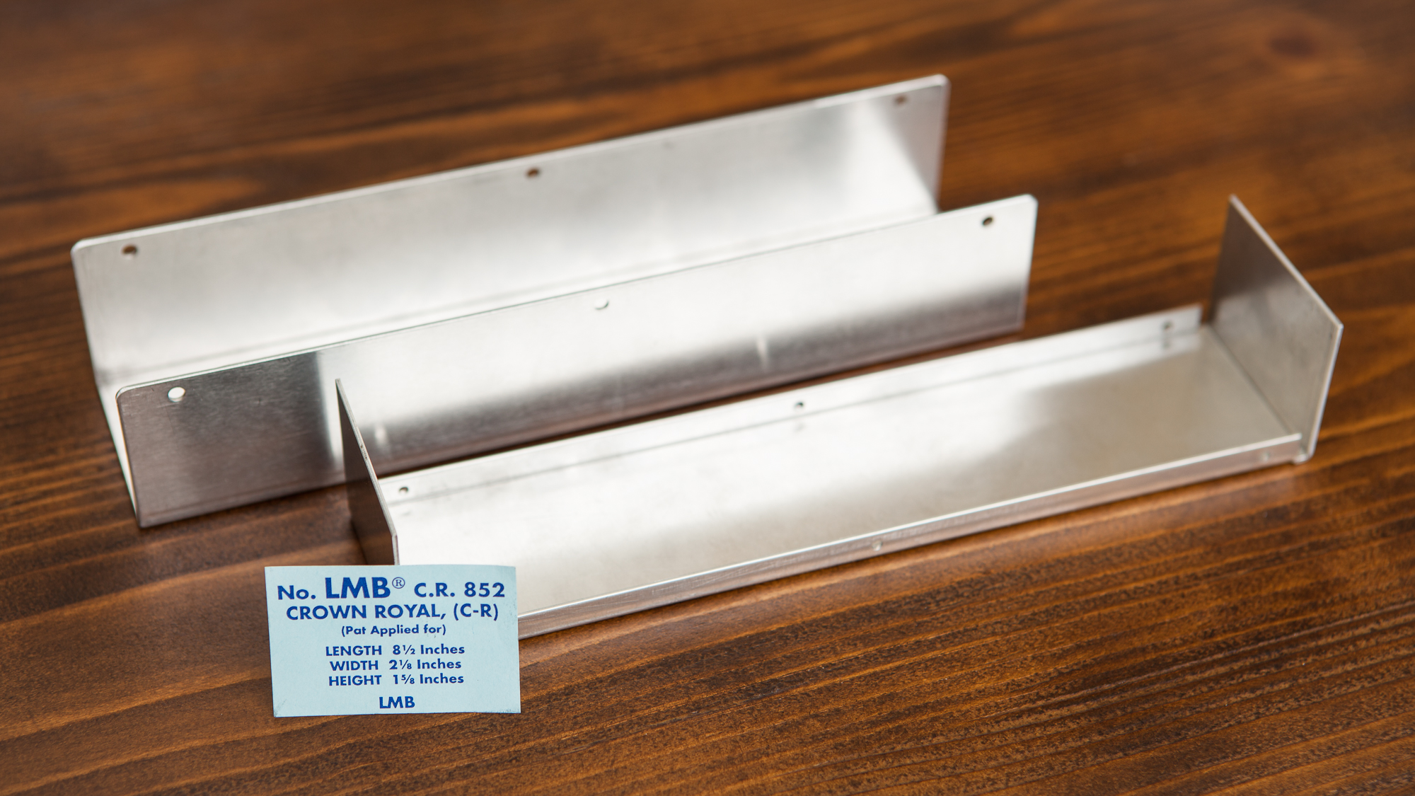
One week later I had the case in my hand. It’s a two-part interlocking ‘U’ design, made from bent aluminum sheet metal. The enclosure’s two parts are completely separate, and are connected using six sheet metal screws included with the case.
Checking Dims
According to LMB Heeger, the case’s dimensions are as follows:
Length: 8 1⁄2 Inches
Width: 2 1⁄8 Inches
Height: 1 5⁄8 Inches
I couldn’t find a datasheet for the C.R. 852 case, and since many companies play fast and loose with their bounding box dimensions my first order of business was checking the exact dimensions of the case.
I was pleasantly surprised to see that case’s outer dimensions were right on the nose. According to my calipers, the case’s measurements were all within +/- 0.005″ of their stated dimensions. +1 for LMB Heeger!
Material and Finish
The C.R. 852 case is made from two pieces of 16 gauge (0.050″) aluminum sheet. I don’t know the alloy, but I’d wager a guess that it’s your standard 6061.
The “plain” version has a lightly brushed finish, although the tooling marks are still visible so I’m assuming it’s the stock finish . Mine arrived with a whole host of scratches on it, but for an industrial case I wouldn’t expect anything less. I’m going to be painting the cases regardless, so this isn’t an issue.
Fastener Holes
The two case halves are held together with six #4 sheet metal screws, included with the case. From my measurements, the through-holes on the outer portion are 0.136″ in diameter (#29 drill bit), while the tapped holes on the inner portion are 0.098″ in diameter (#40 drill bit). The holes are spaced 3.75″ apart.
Modeling
For my own peace of mind, my next step was to create an accurate 3D model to use for the rest of the display design.
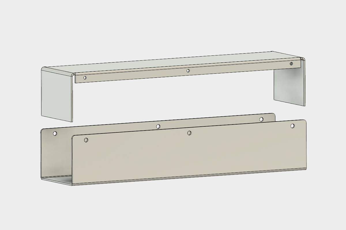
I can use this model to check measurements and clearances as I design the faceplate and circuit board. I can also plan out the modifications I need to make to the case, and use it for designing the larger enclosure later on.
Time Circuit Application
For the time circuit project, I’m going to need three of these cases in a sort of “staircase” pattern on the front of the time circuit enclosure – one for each display.
Suitability
There is something to be said for authenticity, but if I had some decent sheet metal tools I’m not sure I would use these enclosures again. They’re solid well-built enclosures, but they aren’t particularly suited for the application.
For one, the fasteners face out. This means I’ll need to get some flat-head screws and the circuit board cannot be serviced once the faceplate is added.
The case also has rounded edges where the two halves meet. The faceplate for the time circuits has sharp corners, but the rest of the casing won’t match exactly. Another small discrepancy, but notable nonetheless.
Modifications
To use the cases for this project, I’ll need to make a few small tweaks.
Display Opening
This is the big one. Each case will need a rectangular hole approximately 8″ x 1″ to accommodate the LED displays. I’m going to leave the display-specific holes for the faceplate.
Wire Opening
To accommodate the wiring from the circuit board, I’ll also need a hole in the back of the case with a grommet.
PCB Mounting
For the circuit board I’m planning to use the existing holes in the case for mounting. Although because the circuit board spans the height of the case, I’m going to add a mirrored set of holes along the bottom.
To re-use the mounting holes at the top, I’ll also need to drill them out slightly larger and use a machine screw going through the circuit board in place of the sheet metal screws.
Conclusion
And there you have it, all of the details on the LMB Heeger case for the time circuit displays! I always find it useful to start designs by looking at your limitations, and now that I know the form factor and mounting positions for the display casing I can charge forward with the LED display positions, and then the design for the circuit board.
I’m not going to think about the dimensions for the overall enclosure quite yet. One thing at at a time.
Next up: Designing the faceplate
2 Comments
Dale Wallis · April 2, 2018 at 11:19 pm
Hi Dave
How do I sign up to login in?
I am in the process of doing time circuits and would like to follow what you are doing.
Regards Dale
Gold Coast Australia.
Dave · April 8, 2018 at 1:41 am
Hi Dale!
Signing into the site is restricted to administrators at the moment. If you’d like updates from the blog, I believe you can sign up for a WordPress.com account and “follow” the blog to get email notifications.
Dave